
Composite pulverized coal destructive distillation device and method

A technology of pulverized coal and dry distillation, applied in the field of coal chemical industry, can solve the problem of unsatisfactory mixing of heat carrier and pulverized coal, and achieve the effects of easy temperature control, strong adaptability, and low maintenance cost

Inactive Publication Date: 2013-05-22
CHINA COAL ENERGY HEILONGJIANG COAL CHEM +1
View PDF4 Cites 12 Cited by
  • Summary
  • Abstract
  • Description
  • Claims
  • Application Information

AI Technical Summary

Problems solved by technology

[0006] The purpose of the present invention is to provide a coal powder compound carbonization device and method to solve the problem that the heat carrier and coal powder are not ideally mixed in the mixer in the existing coal fluidized carbonization technology, and a long time heat transfer is required to ensure the carbonization effect.

Method used


Image

  • Composite pulverized coal destructive distillation device and method
  • Composite pulverized coal destructive distillation device and method
  • Composite pulverized coal destructive distillation device and method

Examples


specific Embodiment approach 1

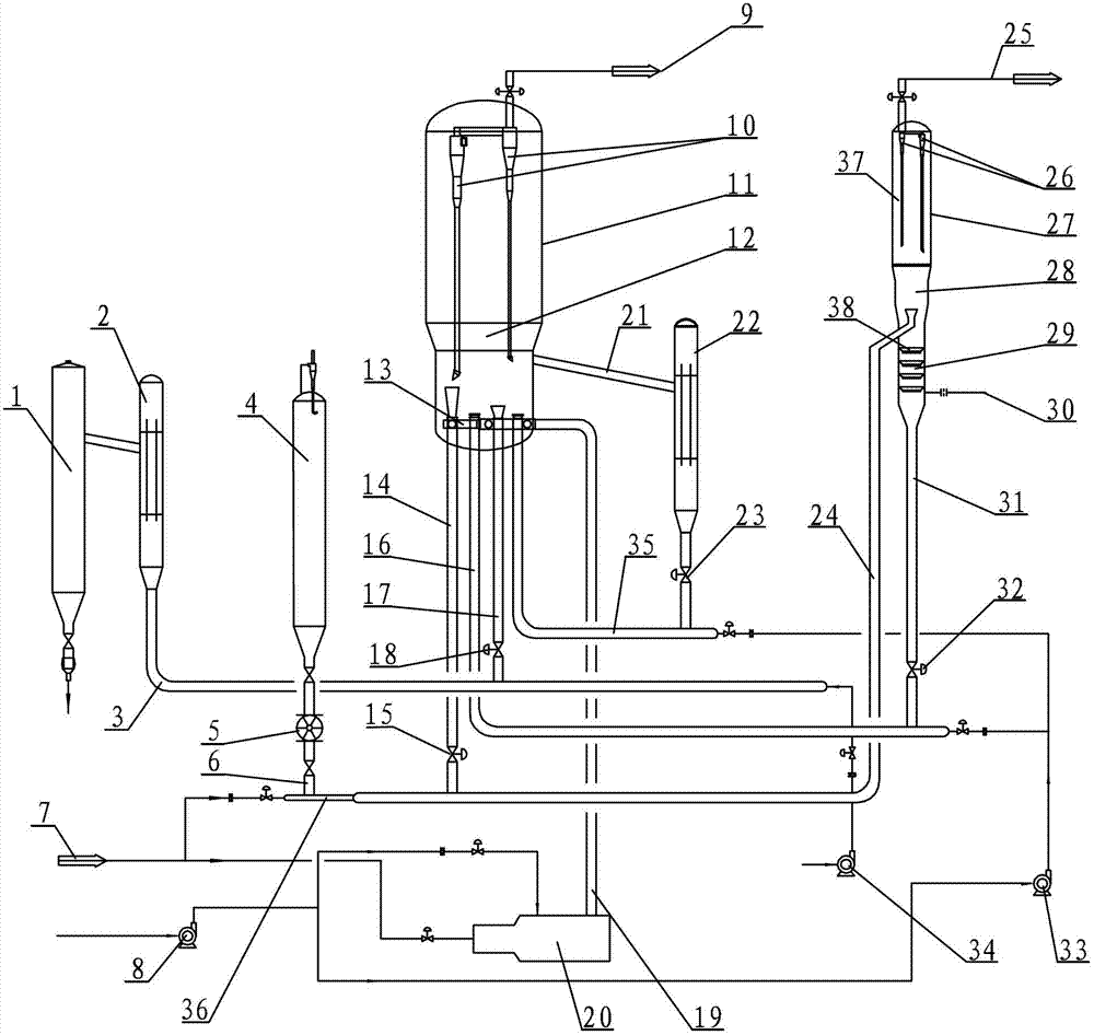
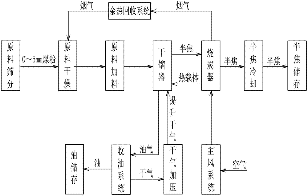
[0021] Specific implementation mode one: combine figure 1 with figure 2Describe this embodiment, which includes a semi-coke storage tank 1, a semi-coke cooler 2, a discharge pipe 3, a raw material tank 4, a feeder 5, a raw material pipe 6, a main fan 8, and a first multistage cyclone 10. Charcoal burner 11, dense phase bed of charcoal burner 12, main air distributor 13, heat carrier standpipe 14, semi-coke conveying pipe 16, discharge standpipe 17, main air pipe 19, auxiliary burner 20, semi-coke Inclined coke tube 21, heat extractor 22, riser reactor 24, second multistage cyclone 26, dry distillation reactor 27, semi-coke descending riser 31, supercharger 33, flue gas machine 34, heat extractor Pipe 35, dry gas inlet pipe 36 and stripping steamer 38, the first multi-stage cyclone 10 is arranged on the upper part in the charcoal burner 11, and the dense phase bed 12 of the charcoal burner is arranged in the middle part in the charcoal burner 11, The charcoal burner 11 uses ...

specific Embodiment approach 2

[0022] Specific implementation mode two: combination figure 1 This embodiment is described. The difference between this embodiment and the first embodiment is that it also adds a heat carrier slide valve 15 installed on the heat carrier standpipe 14 . Other components and connections are the same as those in the first embodiment.

specific Embodiment approach 3

[0023] Specific implementation mode three: combination figure 1 This embodiment is described. The difference between this embodiment and the first embodiment is that it also has a discharge slide valve 18 installed on the discharge standpipe 17 . Other compositions and connections are the same as those in Embodiment 1 or 2.

[0024] Specific implementation mode four: combination figure 1 This embodiment is described. The difference between this embodiment and the first embodiment is that it also adds a heat extraction slide valve 23 , and the heat extraction slide valve 23 is installed on the heat extractor 22 . Other components and connections are the same as those in the third embodiment.


PUM


Abstract

The invention discloses a composite pulverized coal destructive distillation device and method and relates to a pulverized coal destructive distillation device and method so as to solve the problem that a hot carrier and pulverized coal are not ideally mixed in a mixer in the conventional coal fluidization destructive distillation technology. According to the device, one end of a hot carrier vertical pipe is connected with a raising pipe reactor, and the other end of the hot carrier vertical pipe is connected with a charring device; and one end of the raising pipe reactor is introduced with dry gas, and the other end of the raising pipe reactor is communicated with a destructive distillation reactor. The method comprises the following steps: 1, mixing high-temperature semicoke and pulverized coal in the raising pipe reactor, and carrying out a destructive distillation reaction; 2, inputting one part of high-temperature semicoke in the charring device into the raising pipe reactor through the hot carrier vertical pipe, and allowing the other part of high-temperature semicoke to enter a semicoke cooler through a discharging vertical pipe so as to be discharged into a semicoke storage tank after cooling; 3, reacting oil gas and semicoke coke in the destructive distillation reactor; and 4, returning the semicoke fine powder back to the destructive distillation reactor, allowing the semicoke fine powder to enter the charring device to serve as partially combusted semicoke through a semicoke conveying pipe, and raising the temperature to become a hot carrier after combustion. The device and the method are used for destructive distillation of pulverized coalwith the particle size of less than or equal to 5mm.

Description

technical field [0001] The invention relates to a coal powder dry distillation device and method, in particular to a coal powder composite dry distillation device and method, belonging to the field of coal chemical industry. Background technique [0002] Due to the increasing shortage of crude oil resources in the world and the rising oil price, countries all over the world are actively looking for alternative resources for oil. It has become an important supplementary plan to use coal rich in organic matter to produce coal oil through dry distillation technology to replace oil resources. my country is an energy structure rich in coal and low in oil, with coal accounting for about 70% of the total. The dominant position of energy consumption determines the efficient and clean utilization of coal, which is an important way to solve the pollution caused by coal burning and the shortage of oil in our country, and to realize the overall optimization and sustainable development o...

Claims


Application Information

Patent Timeline
IPC IPC(8): C10B53/04
Inventor 宋军胡庆文牛玉梅刘跃张洪慧
Owner CHINA COAL ENERGY HEILONGJIANG COAL CHEM
Learn More