Power distribution cabinet based on ventilation structure and installation method thereof

A technology of power distribution cabinet and installation block, which is applied in the direction of substation/distribution device casing, substation/switchgear cooling/ventilation, etc., which can solve the problem of poor ventilation effect of power distribution cabinet and inability to ensure the normal use and service life of electronic devices. and other problems to achieve the effect of speeding up heat dissipation and air circulation

Pending Publication Date: 2022-07-12
深圳市广鑫创投资发展有限公司
View PDF1 Cites 0 Cited by
  • Summary
  • Abstract
  • Description
  • Claims
  • Application Information

AI Technical Summary

Problems solved by technology

[0003] The purpose of the present invention is to address the poor ventilation effect of the existing power distribution cabinets proposed in the background technology, which cannot effectively cool down and dissipate the power distribution cabinets, and cannot ensure the normal use and service life of the electronic devices in the power distribution cabinets. Problem, propose a power distribution cabinet with good heat dissipation effect and ventilation structure and its installation method

Method used


Image

  • Power distribution cabinet based on ventilation structure and installation method thereof
  • Power distribution cabinet based on ventilation structure and installation method thereof
  • Power distribution cabinet based on ventilation structure and installation method thereof

Examples


Embodiment 1

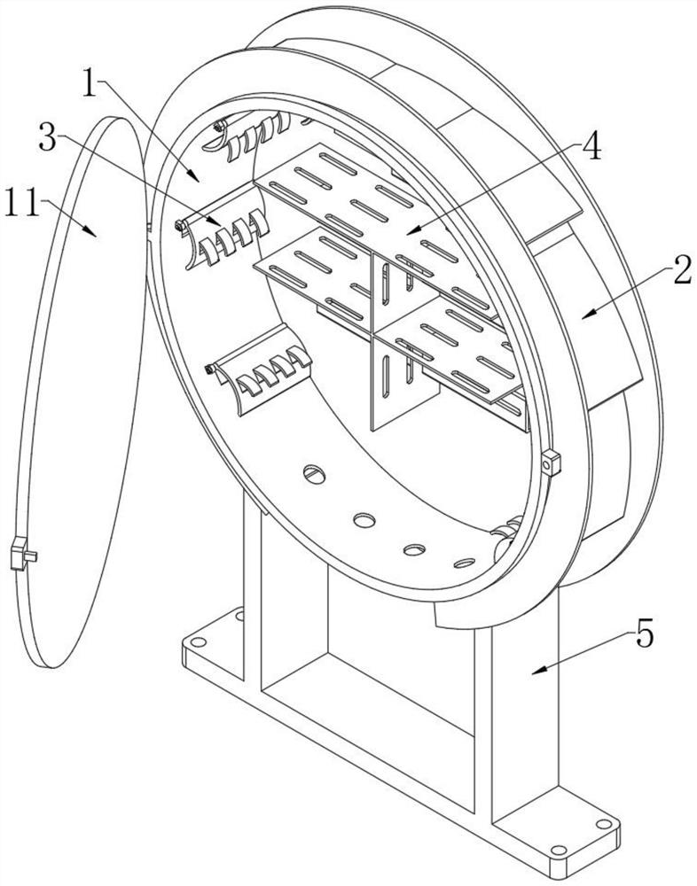
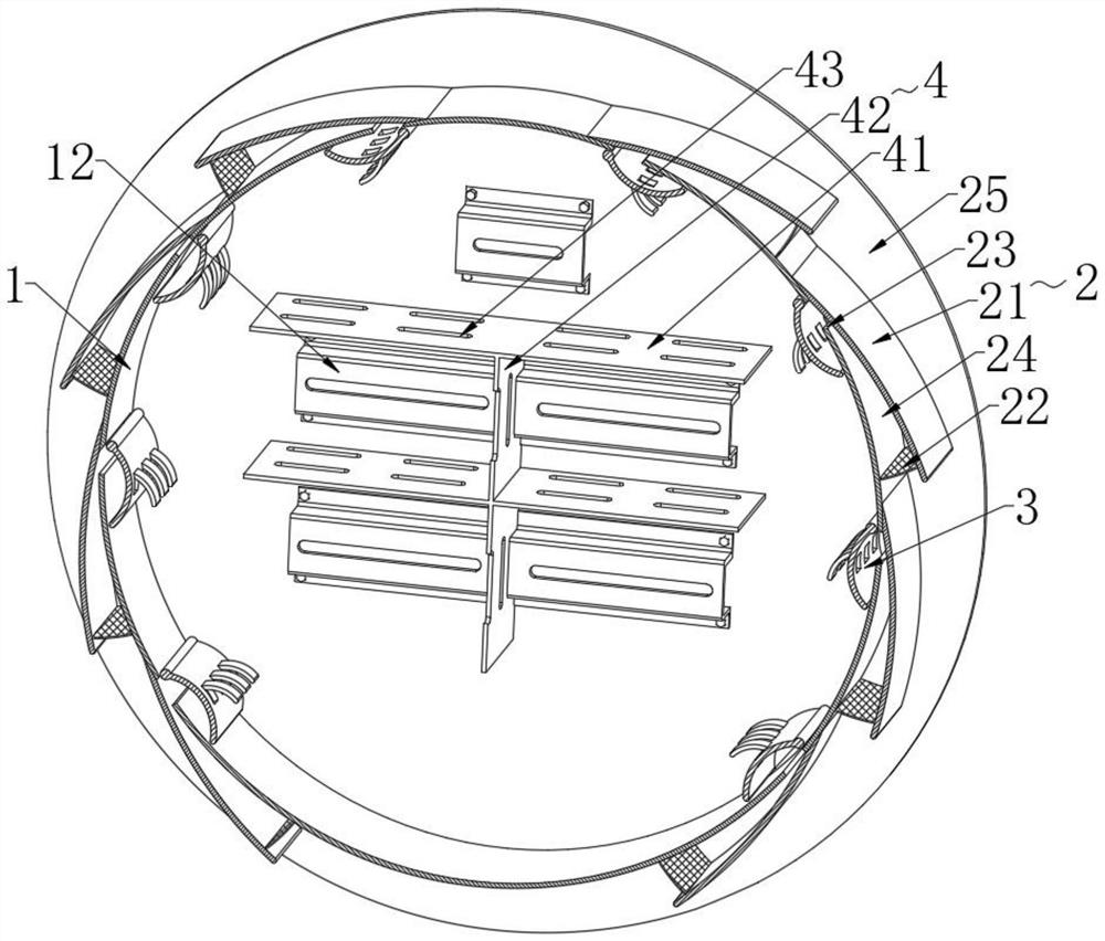
[0031] like Figure 1-3 As shown, a power distribution cabinet based on a ventilation structure proposed by the present invention includes a circular cabinet body 1, the lower side of the cabinet body 1 is provided with a mounting base 5 for supporting the cabinet body 1, and the two outer sides of the cabinet body 1 are provided. Each is provided with a plurality of airflow compression mechanisms 2, and the number of airflow compression mechanisms 2 is set according to actual needs;

[0032] The airflow compression mechanism 2 includes two baffles 25 that are fixed to the outside of the cabinet 1 and are symmetrically arranged in front and rear. A plurality of arc-shaped plates 21 are fixed between the two baffles 25 and the outside of the cabinet 1. The arc-shaped plates 21 and A horn air inlet cavity 24 that gradually narrows from width is formed between the outer walls of the cabinet body 1. The narrow inner side of the horn air inlet cavity 24 is provided with an air inle...

Embodiment 2

[0038] like Figure 4-7 As shown in the figure, a power distribution cabinet based on a ventilation structure proposed by the present invention, compared with the first embodiment, this embodiment also includes an automatic air supply for automatically supplying air to the cabinet body 1 on the rear side of the cabinet body 1 Mechanism 6, the automatic air supply mechanism 6 includes a fan 63 installed on the rear side of the cabinet 1 and a sealed casing 61 that can close and wrap a plurality of airflow compression mechanisms 2. The air outlet end of the sealed casing 61 and the fan 63 passes through a pipe 62 connected, and a cooling mechanism 9 for cooling is installed in the pipeline 62;

[0039] The cooling mechanism 9 includes a water storage tank 92 that is inserted into the pipe 62. The side wall of the pipe 62 is provided with a through hole through which the water storage tank 92 can be inserted. The condensed liquid inside is frozen, and the water storage tank 92 i...

Embodiment 3

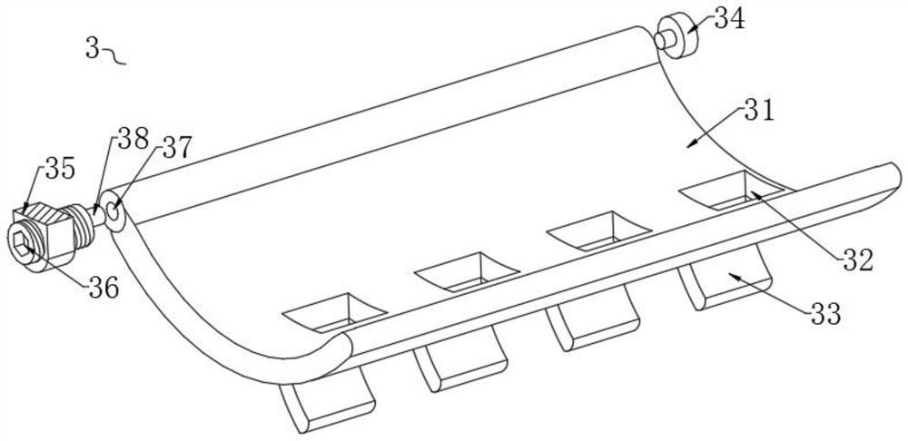
[0043] like image 3 As shown, an installation method applied to the power distribution cabinet of the first implementation:

[0044] S1: Place the arc-shaped air deflector a31 between the inner mounting block 34 and the outer mounting block 35, and align the rotation hole 37 with the rotation rod 38, and then screw the bolt 36, so that the rotation rod 38 enters the rotation hole 37 , the arc-shaped wind deflector a31 can rotate the rod 38 as the origin to turn over its angle, and the arc-shaped wind deflector a31 can be adjusted to a suitable angle;

[0045] S2: When the arc-shaped air deflector a31 is adjusted to a suitable angle, the bolts 36 can continue to be screwed, and the bolts 36 will cooperate with the inner mounting block 34 to clamp and fix the arc-shaped air deflector a31, so as to prevent the arc-shaped air guide The angle of the plate a31 is locked.


PUM


Abstract

The invention relates to the technical field of electrical equipment, in particular to a power distribution cabinet based on a ventilation structure. According to the technical scheme, the cabinet comprises a circular cabinet body, and a plurality of airflow compression mechanisms are arranged on the two outer sides of the cabinet body; the airflow compression mechanism comprises two baffles which are fixed to the outer side of the cabinet body and are symmetrically arranged front and back, a plurality of arc-shaped plates are jointly fixed between the two baffles and the outer side of the cabinet body, and a horn-shaped air inlet inner cavity which becomes narrow gradually is formed between the arc-shaped plates and the outer wall of the cabinet body; an air inlet through hole communicated with the interior of the cabinet body is formed in the narrow inner side of the horn air inlet inner cavity, and a filter screen a is fixed in the horn air inlet inner cavity. After external air flow enters the cabinet body through the horn air inlet inner cavity and the air inlet through holes, the temperature in the cabinet body can be reduced, the air flow entering the cabinet body uniformly enters the cabinet body through the air guide mechanism, effective ventilation and heat dissipation are carried out on the electric parts, and then stable operation of the electric parts in the cabinet body can be ensured.

Description

technical field [0001] The invention relates to the technical field of electrical equipment, in particular to a power distribution cabinet based on a ventilation structure and an installation method thereof. Background technique [0002] Due to the influence of environmental factors such as heat loss and sunshine of the internal electrical components in the outdoor power distribution cabinet, the temperature in the cabinet will rise, and in severe cases, the circuit breaker will be tripped and short-circuited. The authorized announcement number is CN204088959U Chinese utility model patent A distribution cabinet ventilation structure is disclosed, which includes ventilation slots and baffles located on the side walls of the distribution cabinet, at least two ventilation slots are arranged in parallel along the vertical direction, the baffle covers the ventilation slots, and the top surface of the baffle covers the ventilation slots. It is closed and connected to the side wall...

Claims


Application Information

Patent Timeline
Patent Type & Authority Applications(China)
IPC IPC(8): H02B1/56H02B1/28H02B1/30
CPCH02B1/565H02B1/28H02B1/30
Inventor 王玉灵
Owner 深圳市广鑫创投资发展有限公司
Why Eureka
Try Eureka