
Low-voltage power distribution cabinet and fault information remote monitoring method thereof

A technology of fault information and remote monitoring, which is applied in the substation/power distribution device shell, electrical components, circuit devices, etc., can solve problems such as fire, easy damage, and lack of camera protection functions, so as to achieve protection and reduce smoke. Gas concentration, the effect of avoiding economic loss

Pending Publication Date: 2022-07-12
吴芳美
View PDF0 Cites 2 Cited by
  • Summary
  • Abstract
  • Description
  • Claims
  • Application Information

AI Technical Summary

Problems solved by technology

[0003] When the existing low-voltage power distribution cabinet is in use, it cannot monitor its internal faults. When its internal accessories are short-circuited and caught fire, it does not have the fire extinguishing function, which will cause a fire, and it does not have a camera when it is on fire The protection function of the camera will cause the camera to be baked at high temperature, which is easy to be damaged, and it does not have the function of reducing the concentration of smoke generated by the fire.

Method used


Image

  • Low-voltage power distribution cabinet and fault information remote monitoring method thereof
  • Low-voltage power distribution cabinet and fault information remote monitoring method thereof
  • Low-voltage power distribution cabinet and fault information remote monitoring method thereof

Examples


Embodiment Construction

[0038] In order to make the purposes, technical solutions and advantages of the embodiments of the present invention clearer, the technical solutions in the embodiments of the present invention will be clearly and completely described below with reference to the accompanying drawings in the embodiments of the present invention. Obviously, the described embodiments These are some embodiments of the present invention, but not all embodiments. Based on the embodiments of the present invention, all other embodiments obtained by those of ordinary skill in the art without creative efforts shall fall within the protection scope of the present invention.

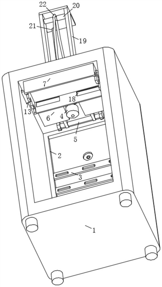
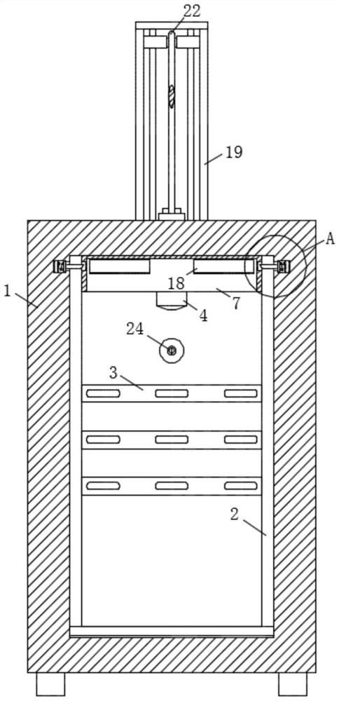
[0039] The invention provides a remote monitoring method for fault information of a low-voltage power distribution cabinet, such as Figure 1-9 shown, including the following steps:

[0040] S1. Perform remote monitoring of fault information through the camera 4 arranged in the power distribution cabinet 1;

[0041] S2. When the c...


PUM


Abstract

The invention discloses a low-voltage power distribution cabinet and a fault information remote monitoring method thereof. The method comprises the following steps: S1, performing fault information remote monitoring through a camera arranged in the power distribution cabinet; s2, when the camera monitors short-circuit fire in the power distribution cabinet, a fire extinguishing mechanism is matched to extinguish fire; and S3, when the fire extinguishing mechanism works, the lifting assembly is matched to lift the camera, so that the camera is moved out of the power distribution cabinet to be protected. The internal condition of the power distribution cabinet can be monitored, automatic fire extinguishing of internal power distribution of the power distribution cabinet can be realized when internal accessories of the power distribution cabinet are short-circuited and on fire, so that economic loss caused by fire disasters is avoided, and the camera can be lifted to leave the power distribution cabinet to be prevented from being baked while fire extinguishing is performed; according to the fire extinguishing device, the camera is protected, smoke generated by fire can be extracted while fire extinguishing is conducted, the smoke concentration can be reduced, and the fire extinguishing device is worthy of application and popularization.

Description

technical field [0001] The invention belongs to the technical field of a low-voltage power distribution cabinet, in particular to a low-voltage power distribution cabinet and a remote monitoring method for fault information thereof. Background technique [0002] Power distribution cabinets (boxes) are divided into power distribution cabinets (boxes), lighting distribution cabinets (boxes), and metering cabinets (boxes), which are the final equipment of the power distribution system. Power distribution cabinet is a general term for motor control center. The power distribution cabinet is used in situations where the load is relatively scattered and there are few circuits; the motor control center is used in the situations where the load is concentrated and there are many circuits. They distribute the electrical energy of a certain circuit of the upper-level power distribution equipment to the nearest load. This class of equipment shall provide protection, monitoring and cont...

Claims


Application Information

Patent Timeline
Patent Type & Authority Applications(China)
IPC IPC(8): H02J13/00H04N7/18H02B1/32H02B1/28A62C3/16A62C35/11A62C37/36A62C99/00
CPCH02J13/00002H02J13/00036H04N7/18H02B1/32H02B1/28A62C3/16A62C3/14A62C35/11A62C37/36A62C99/0045Y02B90/20
Inventor 吴芳美
Owner 吴芳美
Learn More