Limb adjusting device for retinal angiography

A technology of retinal blood vessels and adjustment devices, which is applied in applications, medical science, dental chairs, etc., can solve the problems of reducing diagnostic efficiency, increasing the workload of medical staff, and inability to achieve precise adjustments, so as to improve detection accuracy and achieve pitching Adjustment effect

Pending Publication Date: 2022-07-15
NANTONG UNIVERSITY
View PDF0 Cites 0 Cited by
  • Summary
  • Abstract
  • Description
  • Claims
  • Application Information

AI Technical Summary

Problems solved by technology

[0004] The invention provides a limb adjustment device for retinal angiography, which solves the problem of using a contrast apparatus to perform angiographic diagnosis on the patient's eyes. Azimuth diagnosis, however, only through the patient's own adjustment of the position of the limbs, can not achieve precise adjustment, requires frequent guidance from medical staff, increases the workload of medical staff, and reduces the technical problems of diagnostic efficiency

Method used


Image

  • Limb adjusting device for retinal angiography
  • Limb adjusting device for retinal angiography
  • Limb adjusting device for retinal angiography

Examples


Embodiment 1

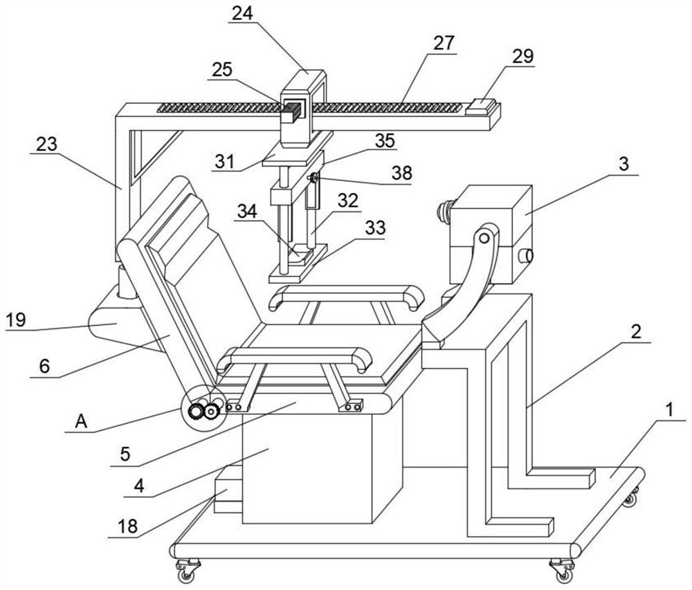
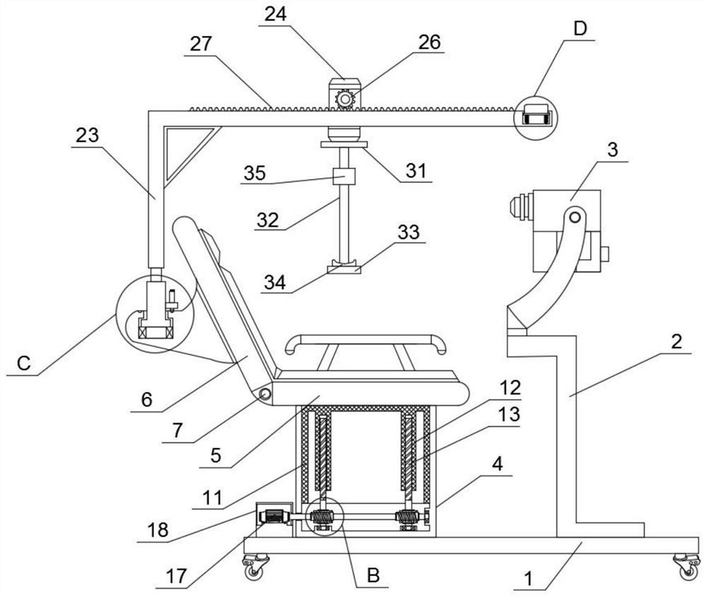
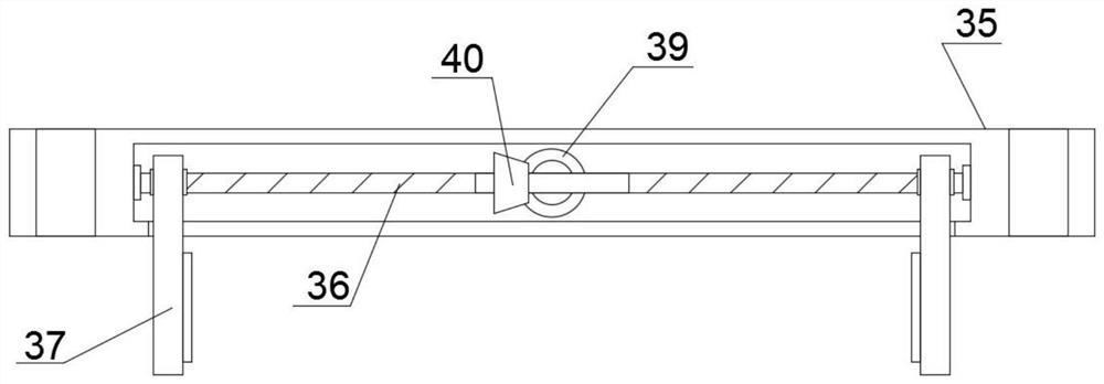
[0031] Example one, by Figure 1-7 Given, a limb adjustment device for retinal angiography includes a base 1 and a detector 3, a mounting frame 2 is fixedly installed on the top of the base 1, the detector 3 is installed on the mounting frame 2, and a hollow is fixedly installed on the top of the base 1 The fixed column 4, the hollow sliding column 11 is slidably connected to the inside of the hollow fixed column 4, the top of the hollow sliding column 11 is fixedly installed with the seat plate 5, and the rear side of the seat plate 5 is connected with the back plate 6 through the rotating adjustment mechanism, and the hollow fixed column 4 There is a lifting mechanism for adjusting the limbs of the patient to move up and down, a fixed seat 19 is fixedly installed on the back of the back plate 6, an electric push rod 20 is rotatably installed on the fixed seat 19, and the electric push rod 20 includes a piston cylinder and a piston rod, A positioning block 21 is fixedly insta...

Embodiment 2

[0032] Embodiment 2, on the basis of Embodiment 1, the outer cover of the second motor 17 is provided with a protective cover 18, the protective cover 18 and the base 1 are fixed by bolts, and the second motor 17 is protected by the protective cover 18 to prevent the The second motor 17 is exposed to the outside without safety guarantee, resulting in the problem of damage.

Embodiment 3

[0033] Embodiment 3, on the basis of Embodiment 1, the moving mechanism includes a slider 24, a third motor 25, a transmission gear 26 and a transmission rack 27, the slider 24 is slidably installed on the support frame 23, and the front of the slider 24 is fixed A third motor 25 is installed, the driving end of the third motor 25 extends to the inside of the slider 24 and a transmission gear 26 is fixedly installed, the transmission rack 27 is fixedly installed on the top of the support frame 23, and the transmission gear 26 rolls with the transmission rack 27 The meshing can adjust the patient's head to move back and forth, thereby realizing the effect of adjusting the patient's head and limbs back and forth.


PUM


Abstract

The invention relates to the technical field of medical equipment, and discloses a limb adjusting device for retinal angiography, comprising a base and a detector, a mounting rack is fixedly mounted at the top of the base, the detector is mounted on the mounting rack, a hollow fixed column is fixedly mounted at the top of the base, and a hollow sliding column is slidably connected in the hollow fixed column; a seat plate is fixedly mounted at the top of the hollow sliding column, a back plate is connected to the rear side of the seat plate through a rotary adjusting mechanism, a lifting mechanism used for adjusting limbs of a patient to move up and down is arranged in the hollow fixing column, and a fixing seat is fixedly mounted on the back face of the back plate. According to the device, medical staff can autonomously adjust the limb position of a patient according to diagnosis requirements, the structure is simple, adjustment is convenient, then the effect of accurate adjustment is achieved, frequent guidance of the medical staff is not needed any more, the workload of the medical staff is relieved, and the diagnosis efficiency is improved.

Description

technical field [0001] The invention relates to the technical field of medical equipment, in particular to a limb adjustment device for retinal angiography. Background technique [0002] Retinal angiography is a technique of injecting a contrast agent from the cubital vein and using confocal laser scanning technology to take fundus photos. Confocal laser scanning technology has strong advantages for detecting the clinical and pathological mechanical properties of tissues, especially in the diagnosis of retinal vascular lesions and cardiovascular diseases. [0003] During retinal angiography observation, it is necessary to inject a contrast agent into the elbow vein first to fix the patient's head and neck limbs, and then use a retinal color camera to diagnose the patient's eyes. During the diagnosis process, the patient needs to adjust the head and neck according to the instructions of the medical staff. The position of the limb is used to cooperate with the medical staff t...

Claims


Application Information

Patent Timeline
Patent Type & Authority Applications(China)
IPC IPC(8): A61B3/00A61B3/12A61B3/15A61G15/04A61G15/06A61G15/12A61G15/10
CPCA61B3/0083A61B3/1241A61B3/15A61G15/02A61G15/125A61G15/10
Inventor 崔进吴辉群席珺婷蔡亦然黄诗涵王志阳朱圣泽赵经委
Owner NANTONG UNIVERSITY
Why Eureka
Try Eureka