Intelligent intracranial pressure detecting and adjusting device

An adjustment device and intracranial pressure technology, applied in the field of medical devices, can solve problems such as detection failure, affecting detection accuracy, and inability to drain drainage of intracranial effusion, so as to improve the efficiency of effusion drainage, save operation time, and increase the success rate Effect

Pending Publication Date: 2022-07-15
SOOCHOW UNIV AFFILIATED CHILDRENS HOSPITAL
View PDF0 Cites 0 Cited by
  • Summary
  • Abstract
  • Description
  • Claims
  • Application Information

AI Technical Summary

Problems solved by technology

[0003] The existing intracranial pressure detection devices have the following technical defects in use: most of the detection devices for intracranial pressure directly contact the effusion in the intracranial cavity through the sensing surface of the detection chip, resulting in electronic components being in contact with the effusion. It is prone to open circuit, which leads to detection failure and affects the detection accuracy. At the same time, when the intracranial pressure is too high, the intracranial effusion cannot be manually drained in time according to the intracranial pressure, resulting in intracranial effusion Excessively affecting the line of sight during the operation, thus affecting the normal operation of the operation, needs to be improved

Method used


Image

  • Intelligent intracranial pressure detecting and adjusting device
  • Intelligent intracranial pressure detecting and adjusting device
  • Intelligent intracranial pressure detecting and adjusting device

Examples


Embodiment 1

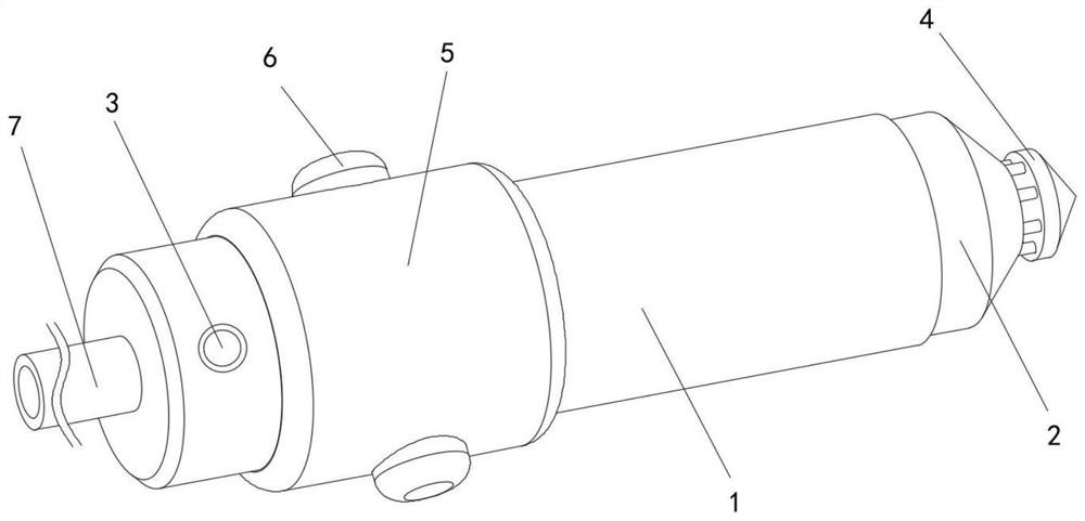
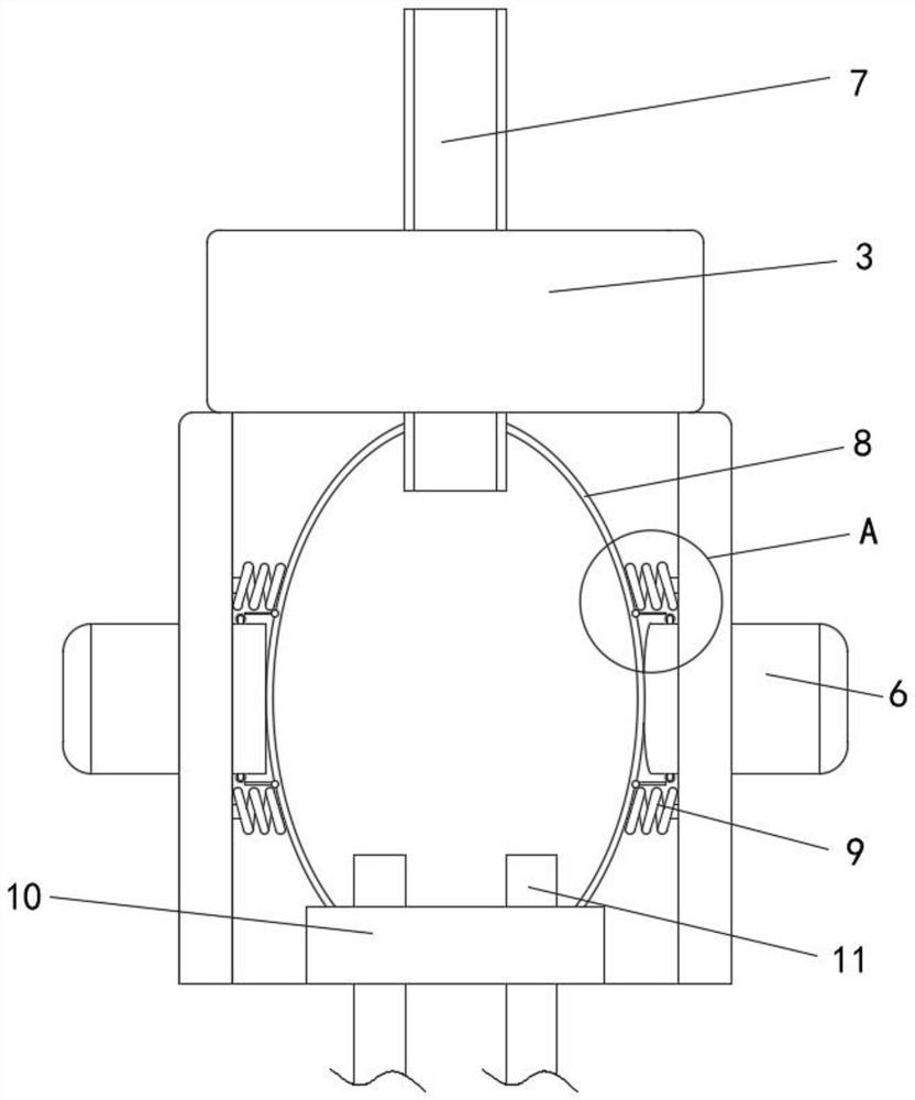
[0035] refer to Figure 1-12, an intelligent intracranial pressure detection and adjustment device, comprising a casing 1, one end of the casing 1 is fixedly installed with a support cylinder 2, and the other end of the support cylinder 2 is fixedly connected with a puncture needle 4 through a plurality of connecting rods. 4. It penetrates to the intracranial area of ​​the surgical patient, and the fluid in the cranial brain enters the interior of the casing 1 evenly through the multiple connecting rod gaps on the inner side of the puncture needle 4. The outer side of the casing 1 is fixedly sleeved with a grip 5, Squeeze keys 6 are slidably installed on both sides of the housing 1, an indicator light 3 is fixedly connected to the outer wall of the housing 1 and located on one side of the hand grip 5, the other end of the housing 1 is fixedly connected with a drainage tube 7, and the There is a manual drainage mechanism inside, and the manual drainage mechanism includes an ela...

Embodiment 2

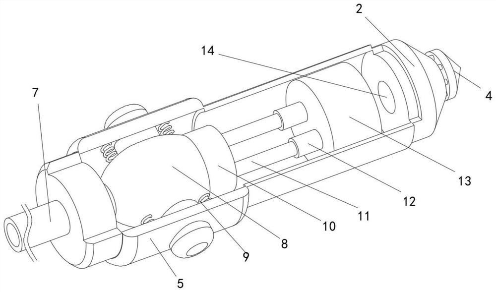
[0037] like Figure 8-10 As shown, this embodiment is basically the same as Embodiment 1. Preferably, the drainage mechanism includes a limit groove 120 opened inside the solenoid valve 12, and a sleeve is fixedly connected to the inner wall of the limit groove 120 on the side close to the conduit 11. 121 , a valve core 123 is slidably installed inside the limiting groove 120 , two movable rods 122 are symmetrically and fixedly installed at one end of the valve core 123 close to the conduit 11 , and the other ends of the two movable rods 122 are slidably penetrated to the inside of the sleeve 121 . The inside of the sleeve 121 is provided with an electromagnetic drive mechanism. When the manual drainage mechanism works, the conductive slide bar 64 contacts the conductive roller 62 to energize and drive the drainage mechanism to open synchronously. The cooperation between the block 125, the movable rod 122 and the valve core 123 realizes the synchronous opening of the solenoid ...

Embodiment 3

[0039] like Figure 9 As shown, this embodiment is basically the same as Embodiment 1. Preferably, the electromagnetic drive mechanism includes a permanent magnet slider 125 fixedly installed at the end of the movable rod 122, and the other end of the permanent magnet slider 125 is fixedly connected with a second spring 126, The other end of the second spring 126 is fixedly connected with an electromagnet 127 , the other end of the electromagnet 127 is fixedly installed on the inner wall of the solenoid valve 12 , and a first through hole 124 is opened in the center of the solenoid valve 12 . During the deformation process, after the electrical driving components of the drainage mechanism are turned on synchronously, the electromagnet 127 is energized, and under the adsorption action of the electromagnetic force, the permanent magnet slider 125 slides toward the side of the electromagnet 127, so that the second spring is energized. 126 is compressed, which in turn causes the v...


PUM


Abstract

The invention discloses an intelligent intracranial pressure detecting and adjusting device which comprises a shell, a supporting cylinder is fixedly installed at one end of the shell, a pricking needle is fixedly connected to the other end of the supporting cylinder through a plurality of connecting rods, the outer side of the shell is fixedly sleeved with a handle, and extrusion keys are symmetrically installed on the two sides of the handle in a sliding mode. An indicator lamp is fixedly connected to the outer wall of the shell and located on the handheld side, a drainage tube is fixedly connected to the other end of the shell, and a manual drainage mechanism is arranged in the shell. The intracranial pressure detection mechanism is used for monitoring the pressure in a craniocerebral cavity in real time in the operation process, and meanwhile an extrusion key, an elastic air bag, a conductive rolling wheel and a conductive sliding rod are arranged in a matched mode to open an electromagnetic valve in time, so that the effect of discharging intracranial high-pressure hydrops in time in the operation process is achieved; the problem that in the prior art, due to too much intracranial hydrops, the operation sight is blocked is solved, and therefore the safety in the operation process is guaranteed.

Description

technical field [0001] The invention relates to the technical field of medical devices, in particular to an intelligent intracranial pressure detection and adjustment device. Background technique [0002] In the field of craniocerebral surgery, it is necessary to monitor the intracranial pressure of patients in real time. The detection accuracy of intracranial pressure directly affects the success rate of the operation. Therefore, it is necessary to accurately detect the intracranial pressure during the operation to ensure the operation. Safety. [0003] The existing intracranial pressure detection devices have the following technical defects in use: most of the intracranial pressure detection devices directly contact the effusion in the intracranial cavity through the sensing surface of the detection chip. It is easy to open circuit, which leads to detection failure and affects the detection accuracy. At the same time, when the intracranial pressure is too large, the intra...

Claims


Application Information

Patent Timeline
IPC IPC(8): A61B5/03A61B5/00A61M1/00
CPCA61B5/031A61B5/6848A61B5/6868A61M2210/0693A61M2210/005
Inventor 张莉周云凤金雪梅
Owner SOOCHOW UNIV AFFILIATED CHILDRENS HOSPITAL
Why Eureka
Try Eureka