Casting production and processing equipment and processing technology thereof
A technology for processing equipment and castings, applied in the field of casting production and processing equipment and its processing technology, can solve the problems of inconvenient multi-directional processing, limited processing range, single processing, etc., and achieve the convenience of remote control equipment operation and stable and firm clamping Effect
- Summary
- Abstract
- Description
- Claims
- Application Information
AI Technical Summary
Problems solved by technology
Method used
Image
Examples
specific Embodiment approach 1
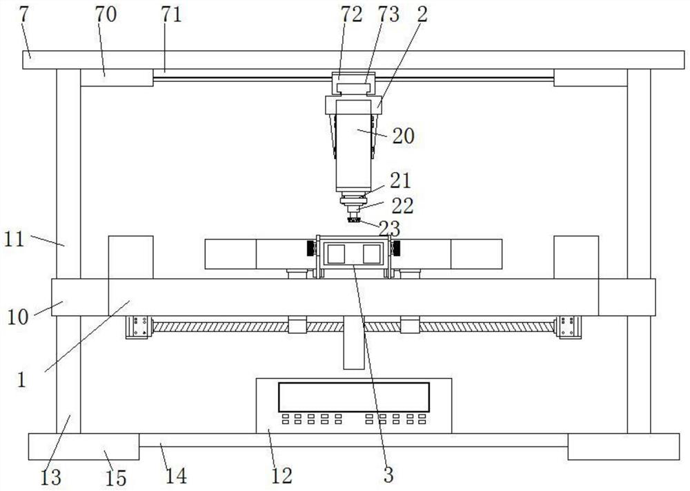
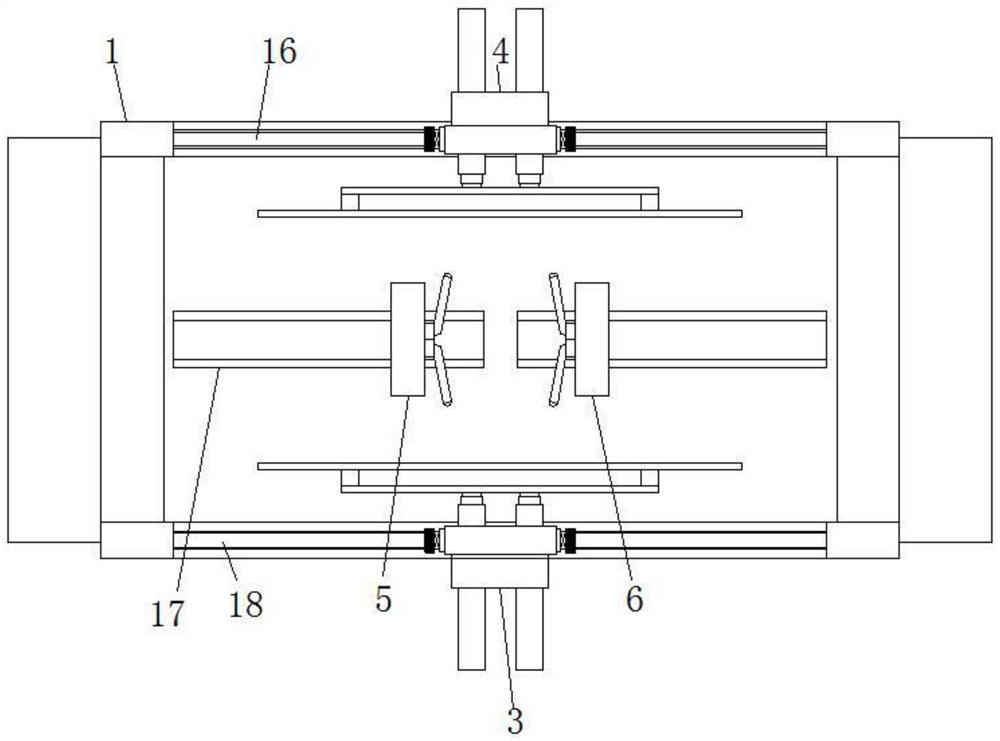
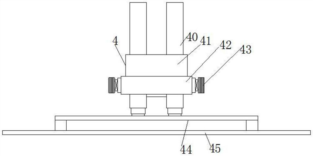
[0037] For the first specific implementation, please refer to Figure 1-8 , The present invention provides a technical solution: a casting production and processing equipment, including a processing table 1, an upper mounting plate 2, a front clamping mechanism 3, a rear clamping mechanism 4, a left clamping mechanism 5, a right clamping mechanism 6 and The top plate 7, the left and right ends of the processing table 1 are fixed with side fixing plates 10, and the front and rear parts of the upper end of the side fixing plate 10 are vertically fixed with a group of upper support rods 11, and the upper ends of the upper support rods 11 are supported under the top plate 7, and An upper mounting plate 2 is arranged under the top plate 7, and a first X-axis linear guide rail 16 and a second X-axis linear guide rail 18 are respectively arranged at the front and rear edges of the upper end of the processing table 1, and the first X-axis linear guide rail 16 slides upward. The rear c...
specific Embodiment approach 2
[0039] Embodiment 2, this embodiment is a further limitation of Embodiment 1. In the present invention, various mechanisms of the startup equipment are operated through the on-site control console 12, and the central processing unit provided in the control console 12 can pass long-distance wireless data. The network signal connection between the transmission module and the remote monitoring center control terminal is convenient for mutual data transfer and for remote control equipment operation, and the use is more intelligent and efficient.
[0040] In this embodiment, upper fixing plates 70 are provided on the left and right parts of the lower end face of the top plate 7, and a third X-axis linear guide rail 71 is arranged between the middle parts of the two sets of upper fixing plates 70 on the left and right sides, and the third X-axis The linear guide 71 is slidably connected with an upper sliding seat 72, the lower part of the upper sliding seat 72 is provided with a firs...
specific Embodiment approach 3
[0041] Embodiment 3 This embodiment is a further limitation of Embodiment 1. In the present invention, the upper sliding seat 72 and the third X-axis linear guide rail 71 , the upper mounting plate 2 and the lower part of the upper sliding seat 72 are arranged under the top plate 7 . The provided first Y-axis linear guide rails 73 are all slidably connected to facilitate changing the displacement of the upper mounting plate 2 on the X and Y axes, so that the processing mechanism can flexibly move left and right, front and rear.
[0042] In this embodiment, a vertical telescopic cylinder 20 is mounted on the upper part of the upper mounting plate 2, a first motor 21 is fixed at the lower end of the vertical telescopic cylinder 20, and a mounting head 22 is provided at the lower end of the first motor 21, and the mounting head A processing tool 23 is mounted on the lower end of the 22 , and the processing tool 23 is a detachable structure.
PUM
 Abstract
Description
Claims
Application Information
 - R&D
- Intellectual Property
- Life Sciences
- Materials
- Tech Scout
- Unparalleled Data Quality
- Higher Quality Content
- 60% Fewer Hallucinations
Browse by: Latest US Patents, China's latest patents, Technical Efficacy Thesaurus, Application Domain, Technology Topic, Popular Technical Reports.
© 2025 PatSnap. All rights reserved.Legal|Privacy policy|Modern Slavery Act Transparency Statement|Sitemap|About US| Contact US: help@patsnap.com


