
Drain valve assembly and washing machine

A drainage valve and component technology, applied in the field of washing machines, can solve the problems of reduced drainage efficiency, limited centrifugal force of centrifugal block, unsatisfactory sealing effect, etc., and achieve the effect of flexible installation position, saving installation space and easy realization

Pending Publication Date: 2022-07-15
QINGDAO HAIER WASHING MASCH CO LTD +2
View PDF1 Cites 0 Cited by
  • Summary
  • Abstract
  • Description
  • Claims
  • Application Information

AI Technical Summary

Problems solved by technology

[0004] However, in the above scheme, the valve plug slides along the radial direction of the inner barrel to open / block the drainage hole, and the sealing effect is not ideal due to the influence of water pressure
At the same time, limited by the rotational speed of the pulsator washing machine, the centrifugal force provided by the centrifugal block is limited, and the drain sealing device may not be able to open the drain hole
Adding a drainage sealing device under the inner barrel occupies the space at the bottom of the inner barrel, which is not conducive to the expansion of the inner barrel
And if the installation position of the drainage sealing device in the above-mentioned scheme is changed, since the valve plug and the centrifugal block slide radially along the inner barrel synchronously, it can only be arranged on the barrel wall of the inner barrel, that is, a drain hole is opened on the barrel wall. Because the drainage hole is set at the bottom of the barrel, the drainage efficiency will be reduced

Method used


Image

  • Drain valve assembly and washing machine
  • Drain valve assembly and washing machine
  • Drain valve assembly and washing machine

Examples


Embodiment 1

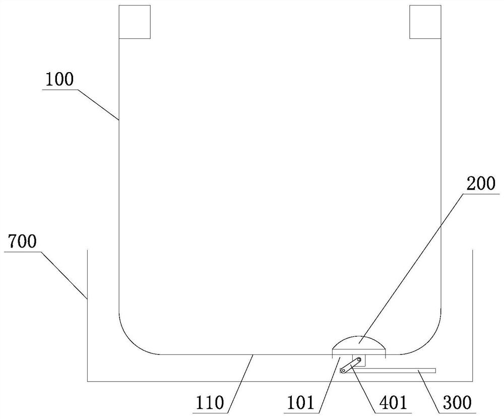
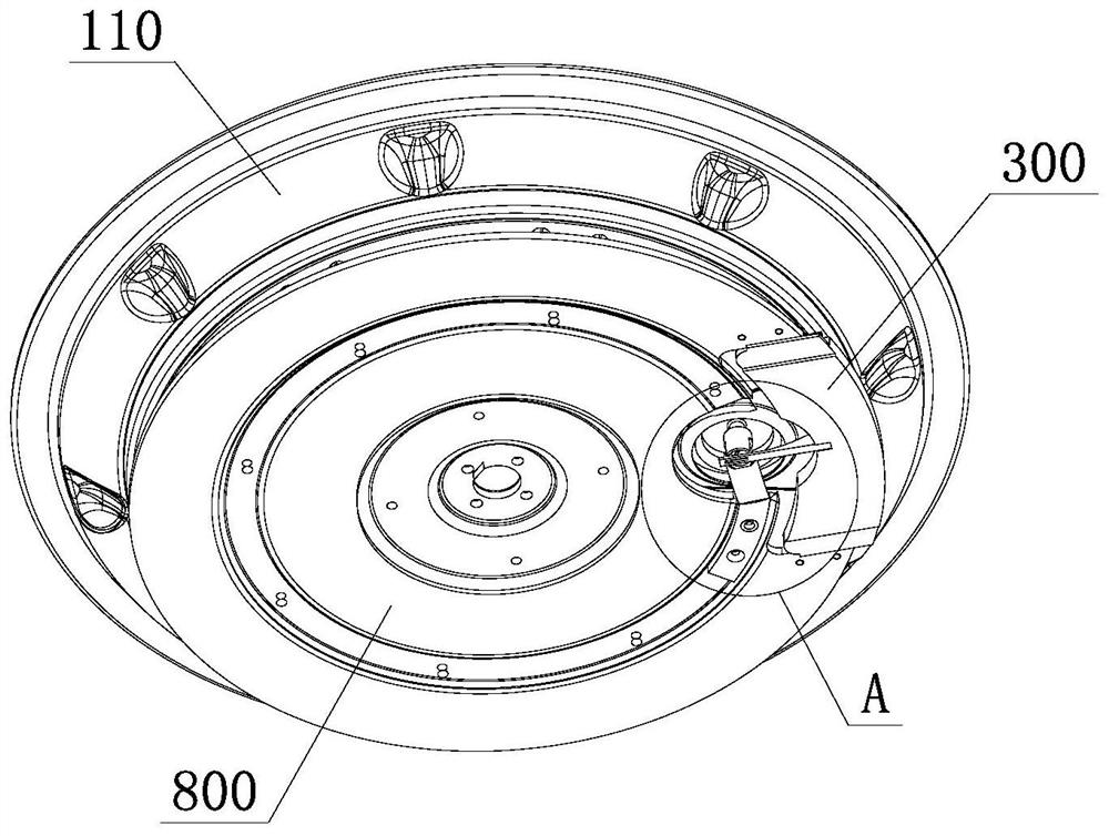
[0056] like Figure 1 to Figure 10 As shown, the drain valve assembly described in this embodiment includes a valve plug 200 and a driving component for driving the valve plug 200 to move. The driving component includes a centrifugal slider 300 and a reversing transmission mechanism, the reversing transmission mechanism is respectively connected with the centrifugal The slider 300 is connected to the valve plug 200 . The centrifugal slider 300 slides under the action of centrifugal force, and drives the valve plug 200 to move through the reversing transmission mechanism. The sliding direction of the centrifugal slider 300 is different from the moving direction of the valve plug 200 .

[0057] In the above solution, the centrifugal slider 300 and the valve plug 200 can move in different directions by setting the reversing transmission mechanism. The drain valve assembly of this embodiment can be applied to a washing machine for centrifugal drainage, such as figure 1 and fi...

Embodiment 2

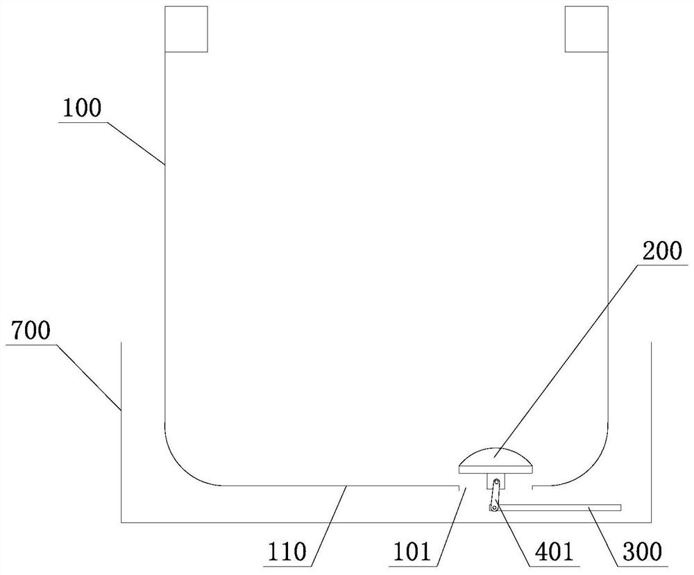
[0095] like Figure 11 and Figure 12 As shown, the difference between this embodiment and the above-mentioned first embodiment is that: the first end 4011 of the reversing rod 401 is set lower than the second end 4012, the centrifugal slider 300 slides horizontally under the action of centrifugal force, and the reversing rod 401 is The centrifugal slider 300 is driven to swing downward, and the valve plug 200 is pulled to move downward.

[0096] In the above solution, when the drain valve assembly is installed on the washing machine, the valve plug 200 is located below the tub bottom 110 of the inner tub 100 to block the drain port 101 from the bottom to the top from the outside of the inner tub 100 . When the inner tub 100 is filled with water, the water pressure at the bottom of the inner tub 100 acts on the sealing cover 201. During the process that the centrifugal slider 300 drives the valve plug 200 to open the water outlet 101, the water pressure at the bottom of the i...


PUM


Abstract

The invention belongs to the technical field of washing machines, and discloses a drain valve assembly and a washing machine, the drain valve assembly comprises a valve plug and a driving part driving the valve plug to move, the driving part comprises a centrifugal sliding block and a reversing transmission mechanism, and the reversing transmission mechanism is connected with the centrifugal sliding block and the valve plug; the centrifugal sliding block slides under the action of centrifugal force and drives the valve plug to move through the reversing transmission mechanism. The sliding direction of the centrifugal sliding block is different from the moving direction of the valve plug. According to the drainage valve assembly, the reversing transmission mechanism is arranged, so that the centrifugal sliding block and the valve plug can move in different directions, when the drainage valve assembly is applied to the washing machine to achieve centrifugal drainage, the installation position of the drainage valve assembly is more flexible, meanwhile, the installation space can be saved, and expansion of an inner barrel of the washing machine is facilitated.

Description

technical field [0001] The invention belongs to the technical field of washing machines, and in particular relates to a drain valve assembly and a washing machine. Background technique [0002] Most of the existing washing machines include an outer tub and an inner tub disposed inside the outer tub, and a plurality of dewatering holes are arranged on the tub wall of the inner tub, so that the inner tub and the outer tub communicate with each other. When the washing machine is working, the outer bucket holds washing water, and the inner bucket holds the laundry to be washed. The washing water can exist between the inner and outer buckets, but this part of the washing water will not be used, resulting in a waste of washing water. Moreover, as the working time of the washing machine increases, the dirt and lint in the washing water will remain in the space between the inner tub and the outer tub, which is difficult to clean, resulting in bacteria and odors caused by perennial u...

Claims


Application Information

Patent Timeline
IPC IPC(8): D06F39/08
CPCD06F39/083
Inventor 吴迪金学峰许升郝兴慧郝世龙劳春峰吕艳芬马双双
Owner QINGDAO HAIER WASHING MASCH CO LTD
Features
  • Generate Ideas
  • Intellectual Property
  • Life Sciences
  • Materials
  • Tech Scout
  • Unparalleled Data Quality
  • Higher Quality Content
  • 60% Fewer Hallucinations
Learn More