Residual water recharge well construction and recharge method based on shallow geothermal utilization

A construction method and technology for recharging wells, which are applied in separation methods, drinking water devices, chemical instruments and methods, etc., can solve the problems of unsatisfactory recharging effects of single wells in recharging wells, and achieve the effect of enhancing the effect of natural recharging.

Pending Publication Date: 2022-07-15
河南省地质矿产勘查开发局第二地质环境调查院
View PDF0 Cites 0 Cited by
  • Summary
  • Abstract
  • Description
  • Claims
  • Application Information

AI Technical Summary

Problems solved by technology

[0005] The purpose of the present invention is to provide a method for construction and recharge of residual water recharge wells based on s

Method used


Image

  • Residual water recharge well construction and recharge method based on shallow geothermal utilization
  • Residual water recharge well construction and recharge method based on shallow geothermal utilization
  • Residual water recharge well construction and recharge method based on shallow geothermal utilization

Examples


Embodiment 1

[0035] Embodiment 1: A kind of residual water recharge well construction method based on shallow geothermal utilization, located in the K3 recharge test well at a certain position in Zhengzhou City, see Figure 1 to Figure 4 , which includes the following steps:

[0036] Step 1: According to the geological and hydrological data of the construction location, according to the stratigraphic structure and groundwater flow direction, determine the location of the well to be located 100m southwest of the intersection and the estimated well depth is 120m.

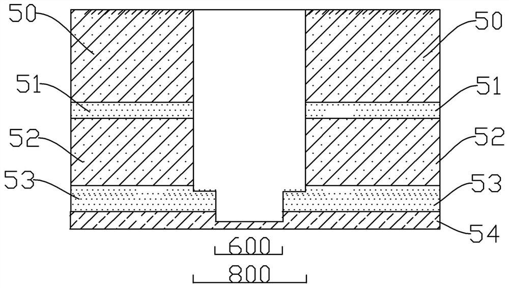
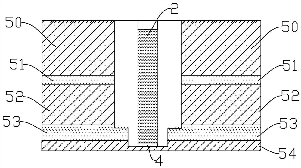
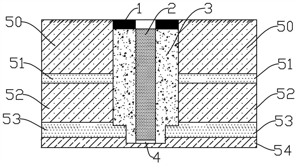
[0037] Step 2: According to the results of physical exploration wells and the cataloging of drilling cores, it is found that strata from 0 to 72.1m are silt, silty clay, silty sand, calcareous nodules and other formations with relatively poor water permeability, and 72.1m to 120m are water permeable A fine-medium sand layer with good properties. The construction depth of the recharge well is determined to be 120m, and the shortes...

Embodiment 2

[0042] Embodiment 2: A method of recharging residual water based on shallow geothermal utilization, see Figure 5 , which includes the following steps:

[0043] Step 1: Use the water pump to discharge the residual water into the recharge well, and the water head height in the well is higher than the groundwater level of the site, resulting in the pressure difference ΔH between the dynamic water level in the well and the groundwater level of the site, and the well water enters the filter material space through the water filter pipe. The pressure difference ΔS between the head pressure and the groundwater of the site is caused in the filter material space.

[0044] Step 2: Control the amount of water pumped by the water pump until the recharge water level does not rise and remains stable, ensuring that ΔH>ΔS.

[0045] Step 3: The water surface of the recharge well rises to the ground level and is still not stable. At this time, the pressurized pump is turned on for pressurized ...


PUM

PropertyMeasurementUnit
Lengthaaaaaaaaaa

Abstract

The invention discloses a residual water recharge well construction and recharge method based on shallow geothermal utilization. The technical problem that the recharge effect of a single well of an existing recharge well is not ideal is solved. The construction method comprises the steps that 1, the well completion position and the predicted well depth are determined; 2, the construction depth and the reducing depth of the recharge well are determined; 3, first well diameter drilling is carried out; step 4, drilling a well with a second well diameter; 5, a precipitation pipe and a water filter pipe are sequentially placed, a filter material is filled to form a water filter layer, and a water stop material is filled to form a water stop layer; the recharge method comprises the following steps of: 1, discharging residual water into the recharge well by using the water pump; 2, the water pumping amount of a water pump is controlled, and delta Hgt is guaranteed; delta S; and 3, when the water surface of the recharge well rises to the ground height and is still unstable, a pressure pump is started for pressurization and recharge. The single well recharge amount can be effectively increased, the number of recharge wells is reduced, space resources are saved, and the construction cost is reduced.

Description

technical field [0001] The invention relates to the technical field of geothermal recharge well backwater, in particular to a residual water recharge well construction and recharge method based on shallow geothermal utilization. Background technique [0002] As a kind of clean and renewable resources, geothermal resources are highly valued at home and abroad. Shallow geothermal energy is a kind of geothermal resource, and it is also the most common and easily exploited geothermal resource. In the development and utilization of shallow geothermal, the groundwater source heat pump system is an energy recycling mode, that is, heat is not taken from water, and water is only used as a circulating medium for geothermal heat energy transfer. During the operation of the groundwater source heat pump system, after the heat extraction is completed, the extracted underground hot water must be manually recharged on the same layer, otherwise it will cause a series of problems. If the gr...

Claims


Application Information

Patent Timeline
IPC IPC(8): E03B3/34E03B3/32B01D36/04
CPCE03B3/34E03B3/32B01D36/04
Inventor 王刚许一川李莹王攀科王烁师永霞王盼盼宋佳王欢周静利范志勇程建强张晋王明闪黄烜王俊杰李沛莹
Owner 河南省地质矿产勘查开发局第二地质环境调查院
Why Eureka
Try Eureka