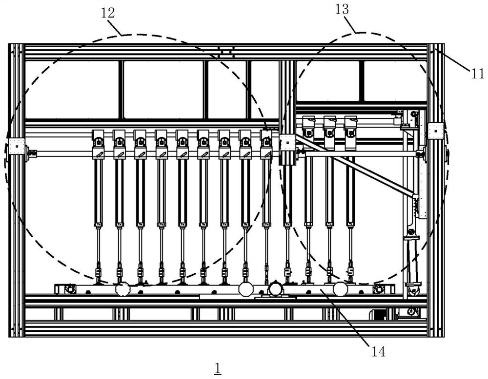
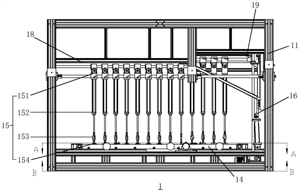
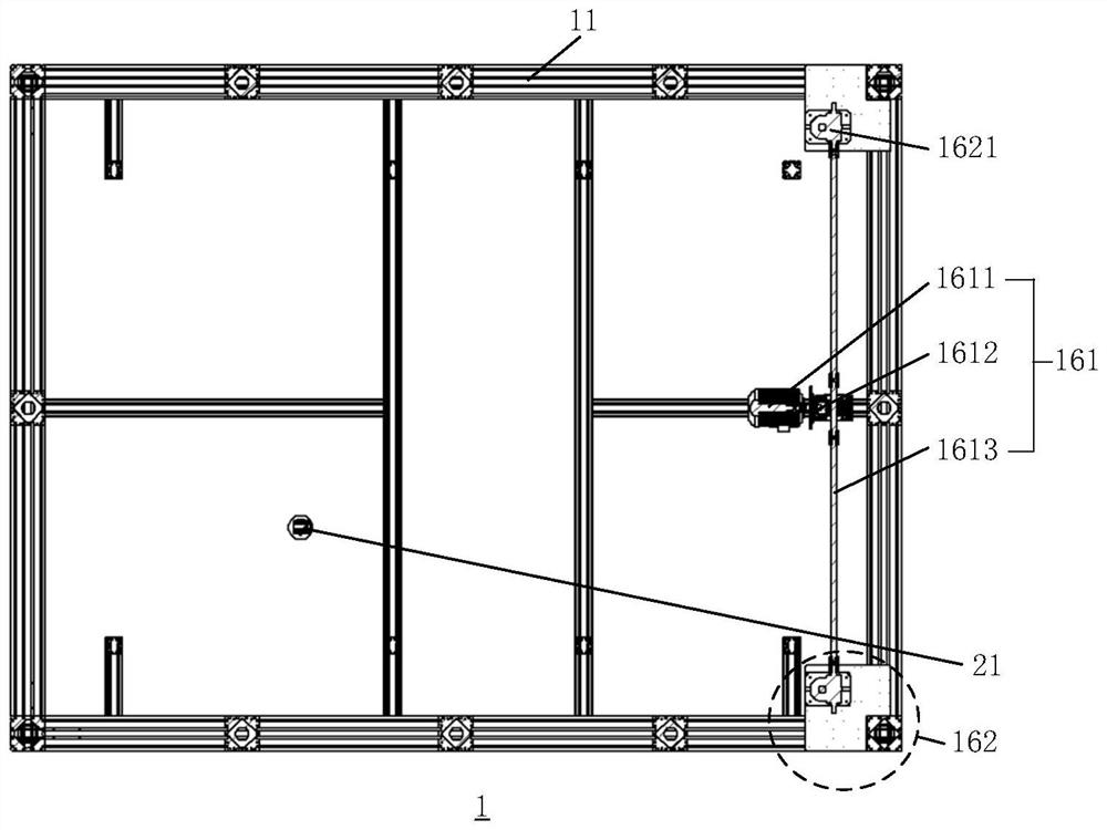
Switchable comprehensive mechanical load test equipment

A technology for testing equipment and mechanical loads, which is applied in the testing of machines/structural components, the use of stable tension/pressure to test the strength of materials, and the testing of optical instruments. It can solve complex equipment manipulation, high cost, and heavy weight of metal sheets problems, to achieve the effect of high safety performance and easy operation

Pending Publication Date: 2022-07-15
WUXI INSPECTION TESTING & CERTIFICATION INST
View PDF0 Cites 3 Cited by
  • Summary
  • Abstract
  • Description
  • Claims
  • Application Information

AI Technical Summary

Problems solved by technology

[0004] The static mechanical load test equipment in related technologies mainly includes three types: airbag type, suction cup type and sand pressure type; among them, the sand pressure type and airbag type mechanical load equipment are not flexible, and the actual pressure of the airbag type components is still controversial ;Dynamic mechanical load equipment mainly includes airbag type and suction cup type; for non-uniform snow load tests, different testing institutions provide different test equipment, and the most common way is to use metal sheets as weight components to exert pressure on components. Each metal block is independently controlled by a chain, and the pressure applied to the component can be changed by increasing the number of metal pieces, but the operation of this method is more complicated.
To sum up, the main disadvantages of existing technologies are as follows: On the one hand, there are not many devices that can realize non-uniform snow load at present; on the other hand, most of the existing non-uniform snow load test equipment uses metal sheets The weight of the metal sheet that exerts pressure on this equipment is too large, which poses a safety hazard to the test personnel. The equipment is complicated to operate, cannot be controlled by the program, and the cost is high. A comprehensive mechanical load test equipment that combines static mechanical load, dynamic mechanical load test and non-uniform snow load

Method used


Image

  • Switchable comprehensive mechanical load test equipment
  • Switchable comprehensive mechanical load test equipment
  • Switchable comprehensive mechanical load test equipment

Examples


Embodiment Construction

[0057] The technical solutions in the embodiments of the present application will be clearly and completely described below with reference to the drawings in the embodiments of the present application. Obviously, the described embodiments are only a part of the embodiments of the present application, but not all of the embodiments. Based on the embodiments in the present application, all other embodiments obtained by those of ordinary skill in the art without creative efforts shall fall within the protection scope of the present application.

[0058] The present application will be further described below with reference to the accompanying drawings and embodiments.

[0059] First, briefly introduce the terms involved in the embodiments of this application:

[0060] Turbine and worm components are used to transmit motion and power between two staggered shafts. The worm wheel and worm are equivalent to gears and racks in their midplane, and the worm is similar in shape to the sc...


PUM


Abstract

The invention relates to switchable comprehensive mechanical load test equipment, and relates to the photovoltaic field. The equipment comprises a profile outer frame, a dynamic and static load unit, a snow load unit and an assembly mounting unit which are all located in a containing space formed by the profile outer frame, the dynamic and static load unit and the snow load unit are both connected with the upper portion of the profile outer frame, and the assembly mounting unit is movably arranged below the dynamic and static load unit and the snow load unit. The photovoltaic module is movably mounted on the module mounting unit; each of the dynamic and static load unit and the snow load unit comprises multiple groups of test assemblies; the snow load unit further comprises a lifting mechanism, and the lifting mechanism is used for driving one end, close to the snow load unit, of the assembly mounting unit to do lifting motion and driving the test assembly of the snow load unit to synchronously lift; a laser range finder is further installed below the assembly installation unit. According to the comprehensive load test equipment for the photovoltaic module, the pressure mode can be adjusted, the pressure intensity can be automatically controlled and collected, and the static load, the dynamic load and the non-uniform load are integrated.

Description

technical field [0001] The present application relates to the field of photovoltaic technology, in particular to a switchable comprehensive mechanical load test equipment. Background technique [0002] With the rapid development of the photovoltaic industry, the increasingly mature solar industry is beginning to realize that the reliability of photovoltaic modules is as important as the power output; therefore, high-quality photovoltaic module manufacturers are integrating reliability testing into the design process and utilizing the test As a result, the quality of modules is fine-tuned during mass production; one aspect of module reliability is resistance to external forces. Since PV modules are installed in different countries and regions, this means that PV modules must withstand the test of various climatic conditions. In addition to general climatic conditions, it also includes extreme climatic conditions such as hurricanes, snow and ice. In order to ensure that photov...

Claims


Application Information

Patent Timeline
Patent Type & Authority Applications(China)
IPC IPC(8): G01N3/12G01N3/08G01N3/14G01M11/08H02S50/10
CPCG01N3/12G01N3/08G01M11/08G01N3/14H02S50/10
Inventor 吴建国其他发明人请求不公开姓名
Owner WUXI INSPECTION TESTING & CERTIFICATION INST
Why Eureka
Try Eureka