
Camera equipment calibration method, electronic equipment and storage medium

A technology of camera equipment and calibration method, which is applied in the field of vision, can solve the problems of low efficiency of camera equipment calibration, limited camera deployment positions, and difficulty in ensuring accuracy, etc.

Active Publication Date: 2022-07-15
SHENZHEN SUPERNODE NETWORK TECH
View PDF18 Cites 0 Cited by
  • Summary
  • Abstract
  • Description
  • Claims
  • Application Information

AI Technical Summary

Problems solved by technology

This strict requirement not only limits the deployment position of the camera, but also varies with the deployment position of the camera equipment, and the movement rules of the corresponding calibration board are also different, resulting in low calibration efficiency for large-scale deployment of camera equipment and it is difficult to ensure the accuracy of the calibration Spend

Method used


Image

  • Camera equipment calibration method, electronic equipment and storage medium
  • Camera equipment calibration method, electronic equipment and storage medium
  • Camera equipment calibration method, electronic equipment and storage medium

Examples


Embodiment Construction

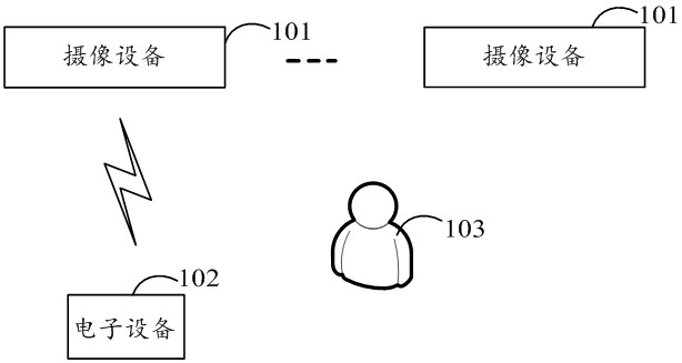
[0026] The technical solutions in the embodiments of the present application will be clearly and completely described below with reference to the accompanying drawings in the embodiments of the present application. Obviously, the described embodiments are part of the embodiments of the present application, rather than all the embodiments. Based on the embodiments in the present application, all other embodiments obtained by those of ordinary skill in the art without creative efforts shall fall within the protection scope of the present application.

[0027] The flowcharts shown in the figures are for illustration only, and do not necessarily include all contents and operations / steps, nor do they have to be performed in the order described. For example, some operations / steps can also be decomposed, combined or combined, so the actual execution sequence may be changed according to the actual situation.

[0028] It should be noted that the camera device calibration method, electr...


PUM


Abstract

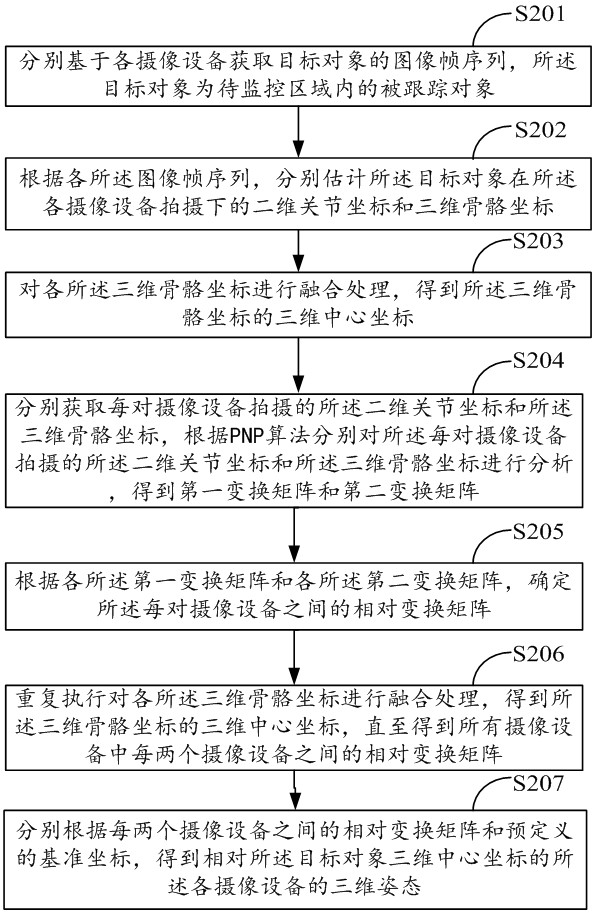
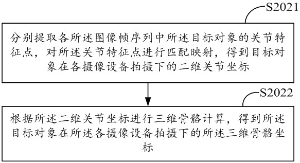
The invention provides a camera device calibration method and device and a storage medium, and the method comprises the steps: obtaining an image frame sequence of a target object based on each camera device, estimating a two-dimensional joint coordinate and a three-dimensional skeleton coordinate of the target object shot by each camera device, and obtaining a three-dimensional center coordinate of the three-dimensional skeleton coordinate; analyzing the two-dimensional joint coordinates and the three-dimensional skeleton coordinates shot by each pair of camera devices according to a PNP algorithm to obtain a first transformation matrix and a second transformation matrix, determining a relative transformation matrix between each pair of camera devices according to each first transformation matrix and each second transformation matrix, and repeating the above steps to obtain a relative transformation matrix between each pair of camera devices; three-dimensional center coordinates of the three-dimensional skeleton coordinates are obtained, and a relative transformation matrix between every two camera devices is obtained; and according to the relative change matrix between every two camera devices and a predefined reference coordinate, obtaining a three-dimensional attitude of each camera device relative to the three-dimensional center coordinate of the target object. The objective of the invention is to improve camera equipment calibration efficiency and calibration accuracy.

Description

technical field [0001] The present application relates to the field of vision technology, and in particular, to a method for calibrating an imaging device, an electronic device, and a storage medium. Background technique [0002] At present, with the application of distributed intelligent camera systems in the fields of artificial intelligence and computer vision, the calibration requirements for multi-camera equipment are getting higher and higher. Because distributed intelligent camera systems often require the deployment of hundreds or even thousands of camera devices for applications such as security, safety, or business analysis. [0003] However, in the actual application process, if the conventional camera calibration method is used to calibrate such a large-scale camera equipment, it is not only necessary to move the calibration plate in front of each camera, but also to ensure that at least two cameras can see the calibration plate at the same time. Plane and calib...

Claims


Application Information

Patent Timeline
Patent Type & Authority Applications(China)
IPC IPC(8): G06T7/80
CPCG06T7/80G06T2207/20081G06T2207/20084
Inventor 区士超布伦诺.卡尔达托刘晓涛
Owner SHENZHEN SUPERNODE NETWORK TECH
Learn More