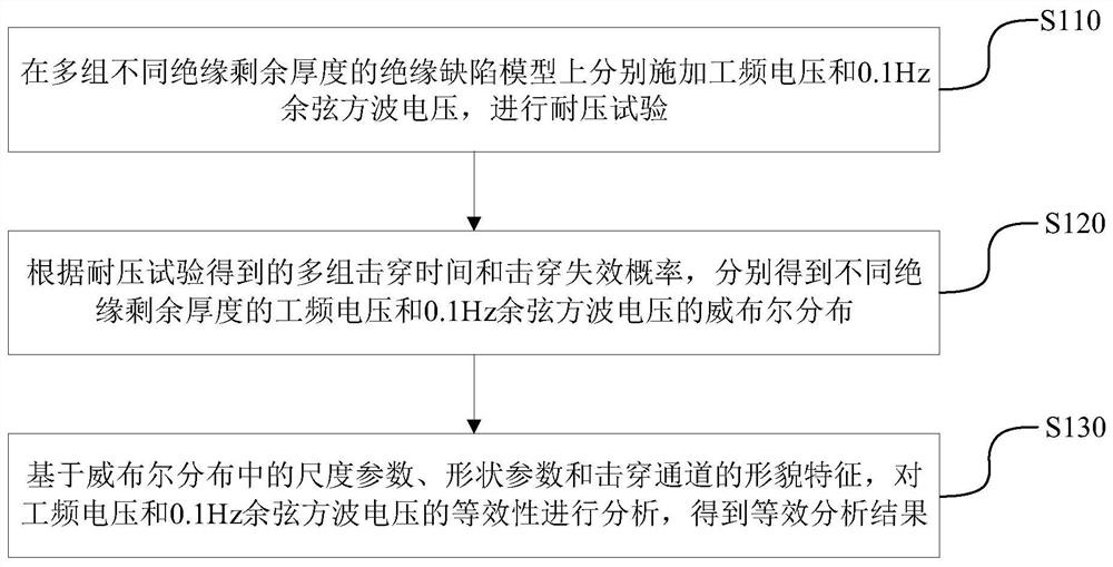
Power cable withstand voltage test method and device based on withstand voltage equivalent analysis, and terminal
A power cable, equivalent analysis technology, applied in the field of power cables, can solve the problem of inaccurate results, and achieve the effect of ensuring accuracy
- Summary
- Abstract
- Description
- Claims
- Application Information
AI Technical Summary
Problems solved by technology
Method used
Image

Examples
Embodiment Construction
[0065] In the following description, for the purpose of illustration rather than limitation, specific details such as specific system structures and technologies are set forth in order to provide a thorough understanding of the embodiments of the present invention. However, it will be apparent to those skilled in the art that the present invention may be practiced in other embodiments without these specific details. In other instances, detailed descriptions of well-known systems, devices, circuits, and methods are omitted so as not to obscure the description of the present invention with unnecessary detail.
[0066] In order to make the objectives, technical solutions and advantages of the present invention clearer, the following descriptions will be given through specific embodiments in conjunction with the accompanying drawings.
[0067] Most of the breakdown accidents of Crosslinked Polyethylene Cable (XLPE) cables are closely related to the main insulation of the power cab...
PUM
 Abstract
Description
Claims
Application Information
PatSnap Eureka turns technology decisions into work you can execute. Powered by our Innovation Knowledge Graph, it runs expert workflows across engineering, life sciences, materials and intellectual property. Get your review-ready output in minutes.


