Spine tractor

A retractor, spine technology, applied in passive exercise equipment, physical therapy and other directions, can solve problems such as adverse effects

Pending Publication Date: 2022-07-22
李强 +1
View PDF1 Cites 0 Cited by
  • Summary
  • Abstract
  • Description
  • Claims
  • Application Information

AI Technical Summary

Problems solved by technology

[0005] The purpose of the present invention is to provide a spinal traction device to so

Method used


Image

  • Spine tractor
  • Spine tractor
  • Spine tractor

Examples


Embodiment 1

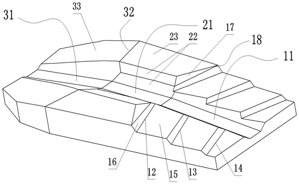
[0045] The spinal retractor in the present invention has an integrated structure, and is molded by one-time foaming of polyurethane to form an elastic support body for supporting the human body. like figure 1 , The spinal distractor is a left-right symmetrical irregular cuboid, and the top surface is an irregular shape, which is spliced ​​by different flat surfaces to achieve corresponding functions; the entire bottom surface is a horizontal plane, which can be placed flat on other objects, such as placing to bed.

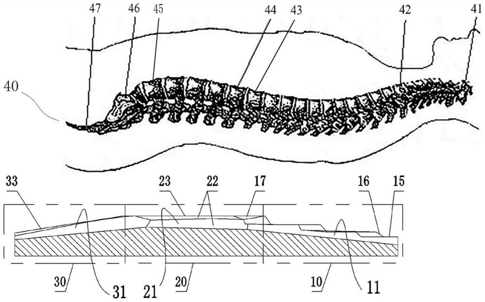
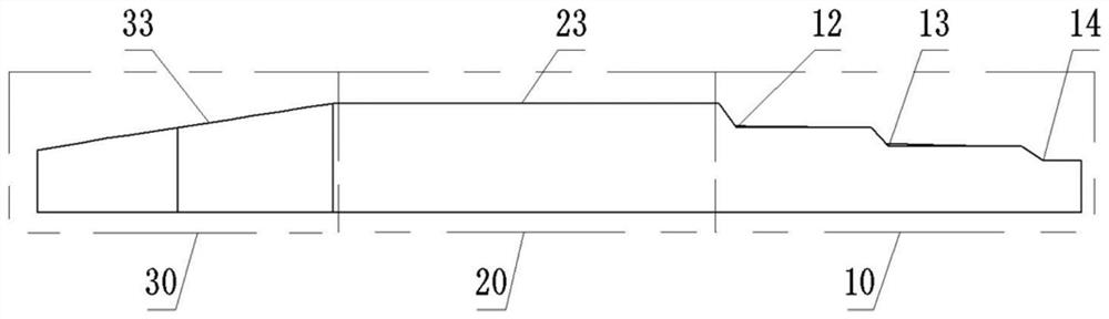
[0046] like figure 1 and image 3 As shown, the spinal distractor is divided into an anterior segment 10, a middle segment 20 and a posterior segment 30 along the length direction, and the top surface of the intermediate segment 20 is higher than the anterior segment 10 and posterior segment 30; Thinning, the rear section 30 is gradually narrowed and thinned backwards, which conforms to the physiological characteristics of the distribution of the muscles of the ...

Embodiment 2

[0059] The difference between this embodiment and Embodiment 1 is that in Embodiment 1, the front section 10 of the elastic support body includes a three-step stepped structure. In the present embodiment, the top surface of the front section 10 is an overall inclined surface, which is similar to the structure of the rear section 30, and relies on the overall inclined plane to generate forward traction on the area above the waist of the human body.

[0060] In other embodiments, only one step may be provided on the front section 10, or two steps may be provided, and more than four steps may also be provided.

Embodiment 3

[0062] The difference between this embodiment and Embodiment 1 is that in Embodiment 1, the rear section 30 and the front section 10 are respectively provided with a sacral support groove 31 and an anterior section escape groove 11 . However, in this embodiment, the top surfaces of the rear section 30 and the front section 10 are flat structures, and no sacral support groove 31 and front section escape groove 11 corresponding to the sacrum are provided. In other embodiments, the sacral support groove 31 may be provided only in the posterior segment 30 , or the anterior segment avoidance groove 11 may be provided only in the anterior segment 10 .


PUM


Abstract

The invention relates to spine traction, in particular to a spine tractor. The spine tractor comprises an elastic supporting body with a front section, a middle section and a rear section. A forward supporting slope is arranged on the front section and used for generating forward inclined elastic supporting force on at least part of the area, located above the waist, of the back of the human body under the pressing of the gravity of the human body, so that forward traction force is generated on the lumbar vertebra of the human body; a backward supporting inclined surface is arranged on the rear section and is used for generating backward inclined elastic supporting force on the area, corresponding to at least one part of the lumbosacral cone, of the back of the human body under the pressing of the gravity of the human body, so that backward traction force is generated on the lumbar vertebra of the human body; the top face of the middle section is higher than the front section and the rear section, a lumbar vertebra avoiding groove penetrating front and back is formed in the middle of the middle section in the left-right direction, and supporting top faces are arranged on the portions, on the left side and the right side of the lumbar vertebra avoiding groove, of the middle section and used for supporting muscular tissue on the left side and the right side of the lumbar vertebra. The spine traction device can solve the problem that some adverse effects can be caused by an existing spine traction mode.

Description

technical field [0001] The present invention relates to spinal traction, in particular to spinal distractors. Background technique [0002] The spine can be divided into cervical, thoracic, lumbar, sacral, and coccygeal vertebrae from top to bottom. Among them, the cervical spine has 7 vertebrae, from top to bottom, C1 vertebrae to C7 vertebrae; thoracic spine has 12 vertebrae, from top to bottom, T1 vertebrae to T12 vertebrae; lumbar spine has 5 vertebrae, from top to bottom, L1 vertebrae Vertebrae to L5 vertebrae; the sacral vertebra has 5 vertebrae fused into a single piece called the sacrum; the coccyx has 4 vertebrae fused into a single piece called the coccyx. The vertebrae gradually thicken from top to bottom. There is a hole in the center of the vertebrae. The holes in the center of each vertebra are connected and called the spinal canal, which is used to accommodate the spinal cord and protect the spinal cord. The upper and lower notches of adjacent vertebrae encl...

Claims


Application Information

Patent Timeline
IPC IPC(8): A61H1/02
CPCA61H1/0222
Inventor 李奕东
Owner 李强
Why Eureka
Try Eureka