Self-locking structure of drill chuck

A technology of self-locking structure and drill chuck, which is applied in the direction of tool joints, etc., can solve problems such as failure to work normally, work safety and reliability to be improved, self-locking function failure, etc., to achieve simple and effective buckle mode and operation mode, and improve Effects of operational reliability, ease of manufacture and assembly

Inactive Publication Date: 2022-07-22
ZHEJIANG CHAOLI MECHANICAL TOOLS
View PDF1 Cites 0 Cited by
  • Summary
  • Abstract
  • Description
  • Claims
  • Application Information

AI Technical Summary

Problems solved by technology

The above operation is because the spring piece is set inside, and the operation process needs to manually twist the rotating sleeve, and it needs to be kept, otherwise the spring piece cannot be effectively stuck due to the reverse force of the drill body
And if the reverse torque of the drill body is large, the spring piece will be damaged or bent, and it will be stuck inside and cannot work normally.
[0004] On the other hand, during work, the vibration will cause the above self-locking function to fail, and the spring piece cannot be effectively clamped on the ratchet part of the drill body
[0005] Under the above working environment, we found that the work safety and reliability of this structure still needs to be improved

Method used


Image

  • Self-locking structure of drill chuck
  • Self-locking structure of drill chuck
  • Self-locking structure of drill chuck

Examples


Embodiment 1

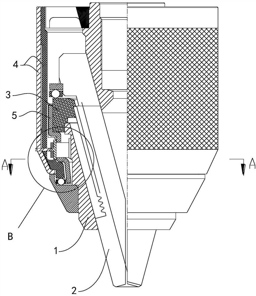
[0029] A self-locking structure of a drill chuck, refer to figure 1 As shown, it includes a drill body 1 , a clamping jaw 2 , a nut 3 , and a rotating sleeve 4 . The drill body 1 is installed vertically, and there are three clamping jaws 2. The clamping jaws 2 penetrate the drill body 1 obliquely and move in the inclined direction to realize opening and closing. , the back of each jaw 2 has a threaded structure. The rotating sleeve 4 and the nut 3 are clamped and fixed. The rotation of the rotating sleeve 4 can drive the nut 3 to rotate, and the nut 3 realizes the oblique movement of the clamping jaw 2 on the drill body 1 through the cooperation of the threads, so as to realize the opening and closing clamping operation. The screwdriver can be assembled in the clamping jaw 2 , and then a motor can be connected to the upper end of the drill body 1 to drive the drill body 1 to rotate.

[0030] combine figure 1 , image 3 and Figure 4 It can be seen that a ratchet portion ...

Embodiment 2

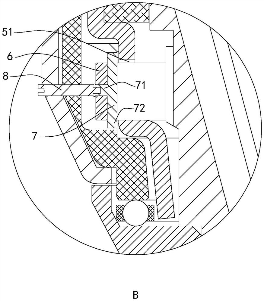
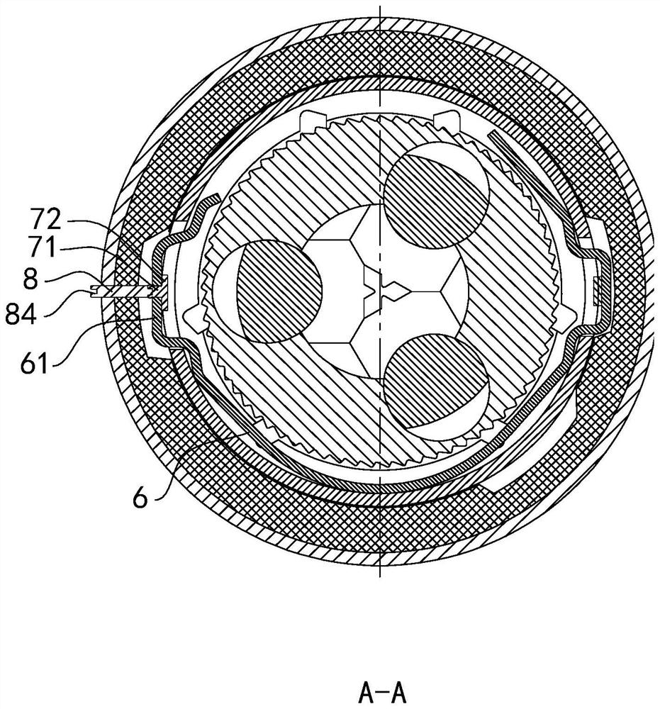
[0037] Based on Example 1, refer to Figure 5 and Image 6 As shown, in order to realize the linkage between the connecting rod 8 and the locking piece 7, the connecting rod 8 and the locking piece 7 are provided with an inner hole 85, the inner hole 85 is provided with a rope body 9, and one end of the rope body 9 is fixed on the locking piece 7, the rope body 9 passes through the locking piece 7 and the connecting rod 8 and extends out of the connecting rod 8. The rope body 9 can be pulled, so that the connecting rod 8 and the rotating shaft 71 can be connected more quickly, or the elastic spring plate 6 can be pulled by pulling the rope body 9, so that the elastic spring plate 6 can be kept away from the ratchet portion 11 .

[0038] In order to facilitate the operation of the connecting rod 8 , a tool slot 84 is provided on the outer end of the connecting rod 8 . The tool slot 84 is a "cross" slot or a "one" slot.

[0039]The design of the locking piece 7 has multiple e...


PUM


Abstract

The invention discloses a self-locking structure of a drill chuck, belongs to the technical field of drill chuck tools, solves the problem of adjustment and control of an elastic reed, and adopts the technical scheme that a buckling piece is arranged on a bent convex body of the elastic reed, the buckling piece is rotationally connected with the bent convex body, a channel is formed in a rotary sleeve, and the elastic reed is rotationally connected with the channel. The channel right faces the rotating shaft of the lock catch piece, a connecting rod is inserted into the channel, one end of the connecting rod is fixedly matched with one end of the rotating shaft in an inserted mode, the effect of adjusting and controlling the elastic reed is achieved, and working reliability and safety are improved.

Description

technical field [0001] The invention relates to the field of drill chuck tools, in particular to a self-locking structure of a drill chuck. Background technique [0002] At present, the Chinese Patent Application Publication No. CN 110961666 A discloses a self-locking drill chuck, which includes a rotating sleeve, a drill body, a nut, a nut sleeve fixedly connected with the nut, a clamping claw, and a self-locking structure. The structure includes a tooth and a spring piece, the spring piece has a locking end matched with the tooth, a connecting protrusion, and the rotating sleeve has a first part connected with the spring piece connecting protrusion in a self-locking state and a non-self-locking state. The second part connected with the connecting protrusion of the spring piece and the cam structure for controlling the locking end of the spring piece. [0003] In the prior art, this structure realizes the deformation of the spring piece by twisting the rotating sleeve, and...

Claims


Application Information

Patent Timeline
Patent Type & Authority Applications(China)
IPC IPC(8): B23B51/12
CPCB23B51/12
Inventor 王乾赵强
Owner ZHEJIANG CHAOLI MECHANICAL TOOLS
Why Eureka
Try Eureka