
Transmission support and sliding device

A technology of transmission bracket and sliding device, which is applied in the direction of feeding device, metal processing equipment, metal processing machinery parts, etc. It can solve the problem that the resistance of the screw is large or small, which affects the position accuracy of the slide table and the force of the screw in the screw system. Uncertain size and direction etc.

Pending Publication Date: 2022-07-22
BEIJING SEMICORE PRECISION MICROELECTRONICS EQUIP CO LTD
View PDF8 Cites 0 Cited by
  • Summary
  • Abstract
  • Description
  • Claims
  • Application Information

AI Technical Summary

Problems solved by technology

[0004] However, when the parallelism of the above-mentioned lead screw transmission system is low, the magnitude and direction of the force acting on the lead screw are indeterminate, which causes the resistance to the rotation of the lead screw to fluctuate, which in turn affects the movement of the slide table in the lead screw system. Position accuracy

Method used


Image

  • Transmission support and sliding device
  • Transmission support and sliding device
  • Transmission support and sliding device

Examples


Embodiment 1

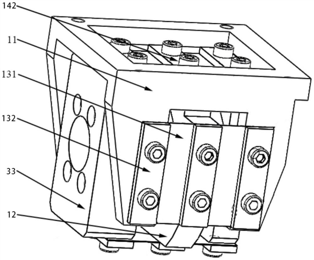
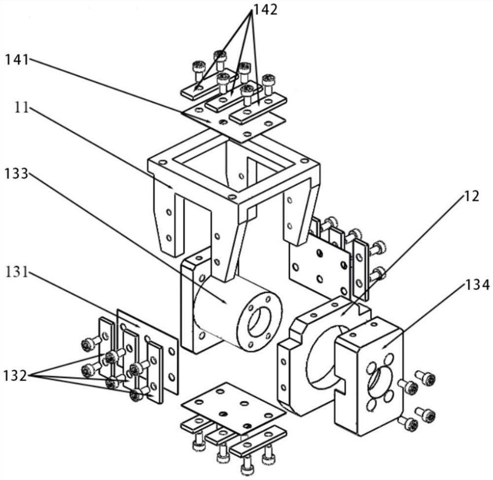
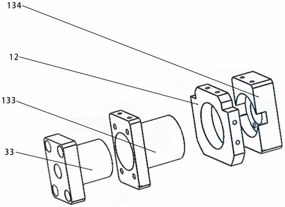
[0043] This embodiment provides a transmission bracket 1, such as Figure 1 to Figure 3 As shown, it includes a bracket body 11, a force transition piece 12, a first elastic structure 13 and a second elastic structure 14. The bracket body 11 is fixedly connected with the sliding assembly, and the force transition piece 12 is installed between the drive assembly and the bracket body 11. During this time, the first elastic structure 13 is installed between the force-bearing transition piece 12 and the drive assembly, the second elastic structure 14 is installed between the bracket body 11 and the force-bearing transition piece 12, and the bracket body 11 is sleeved on the force-bearing transition piece 12 In addition, the force transition piece 12 is a rounded rectangular ring. The force transition piece 12 receives the driving force of the driving component through the first elastic structure 13 and transfers the driving force to the bracket body 11 through the second elastic st...

Embodiment 2

[0048] This embodiment provides a sliding device, such as Figure 4 As shown, it includes a base 2, a driving assembly, a sliding assembly and the transmission bracket 1 in Embodiment 1, the driving assembly is arranged on the base 2, the sliding assembly is fixedly connected with the base 2, and the transmission bracket 1 is arranged on the base 2. between the seat 2 assembly and the sliding assembly.

[0049] like Figure 4 As shown, in the sliding device provided in this embodiment, the sliding component includes a sliding table 41 and a sliding rail 42, and the driving component includes a driving member, a screw rod 31 and a nut member 32. The driving member is a servo motor, and the driving member is fixed to the base by bolts. One end of the seat 2, the driving end of the driving member is connected with the screw rod 31, the two screw rod 31 supports are respectively arranged at both ends of the screw rod 31, the screw rod 31 is slidably connected with the screw rod 3...


PUM


Abstract

The invention discloses a transmission support and a sliding device.The transmission support comprises a support body, a stress transition piece, a first elastic structure and a second elastic structure, the support body is installed between a driving assembly and a sliding assembly, and the stress transition piece is installed between the driving assembly and the support body; the first elastic structure is suitable for being installed between the stress transition piece and the driving assembly, the second elastic structure is suitable for being installed between the support body and the stress transition piece, and the stress transition piece has the characteristics that the first elastic structure bears driving force on the side of the driving assembly through the first elastic structure; and the driving force is transferred to the force transmission state of the bracket body through the second elastic structure. The nut is sleeved with the transmission support, the driving force of the driving assembly side is borne through the first elastic structure, the driving force is transferred to the support body through the second elastic structure, the force borne by the lead screw is effectively buffered, the deflection change of the lead screw is reduced, and therefore friction between the lead screw and the nut is reduced, and the position precision of the sliding table is improved.

Description

technical field [0001] The invention relates to the technical field of mechanical equipment, in particular to a transmission bracket and a sliding device. Background technique [0002] The screw drive system is one of the important structures of the machine tool, which mainly includes the drive motor, the screw nut pair, the bearing and other accessories. Movement, the accuracy and stability of its movement process directly affect the performance of the machine tool. [0003] The existing lead screw transmission system is realized by the lead screw directly driving the slide table and matching the lead screw nut and the slide rail, including the base, the slide rail, the slide table, the driving part, the lead screw and the lead screw nut, and the slide rail is arranged on the base. On both sides of the slide table, the slide table is slidably connected to the slide rail, the slide table is provided with a mounting groove, the lead screw nut is fixedly connected with the sl...

Claims


Application Information

Patent Timeline
Patent Type & Authority Applications(China)
IPC IPC(8): B23Q5/40B23Q1/25
CPCB23Q5/40B23Q1/25
Inventor 于静王文举李婷赵磊廉金武郭益言梅辰萌
Owner BEIJING SEMICORE PRECISION MICROELECTRONICS EQUIP CO LTD
Learn More