Soap uniform sectioning equipment for production and processing

A technology of cutting and soaping, which is applied in metal processing, cutting soap, etc., can solve problems such as reducing work efficiency, and achieve the effect of increasing moving speed

Pending Publication Date: 2022-07-22
李彪
View PDF1 Cites 0 Cited by
  • Summary
  • Abstract
  • Description
  • Claims
  • Application Information

AI Technical Summary

Problems solved by technology

[0005] In order to overcome the shortcomings of existing soap cutting machines that need to manually adjust the double-ear nuts, which will reduce people's work efficiency, the technical problem of th...

Method used


Image

  • Soap uniform sectioning equipment for production and processing
  • Soap uniform sectioning equipment for production and processing
  • Soap uniform sectioning equipment for production and processing

Examples


Embodiment 1

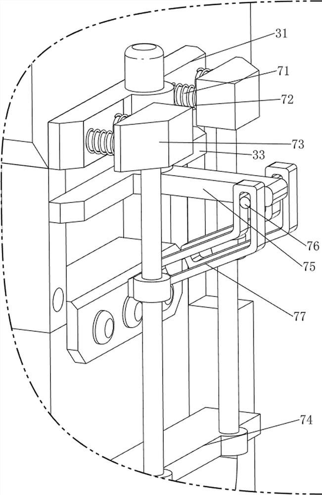
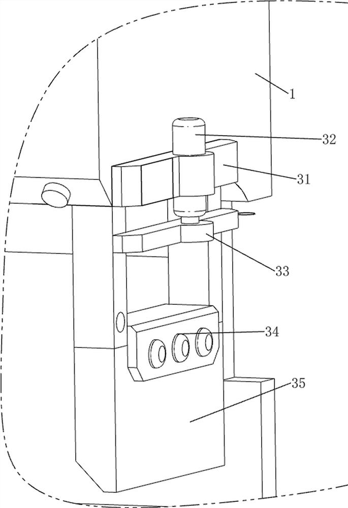
[0033] A device for uniformly cutting soap for production and processing, such as Figure 1-5 As shown, it includes an outer casing 1, a card seat 2, a cutting mechanism 3 and a transmission mechanism 4. The lower right side of the outer casing 1 is provided with a clamping seat 2 through bolts, the outer casing 1 is provided with a cutting mechanism 3, and the outer casing 1 is provided with a transmission mechanism 4 , the conveying mechanism 4 is used for conveying soap. The cutting mechanism 3 includes a first fixing block 31, an electric push rod 32, a push frame 33, a tool holder 34 and a cutter 35. The upper right side of the housing 1 is provided with a first fixing block 31 through bolts, and the middle of the first fixing block 31 is provided with The electric push rod 32, the bottom of the telescopic rod of the electric push rod 32 is welded with a push frame 33, the telescopic rod of the electric push rod 32 can drive the push frame 33 to move up and down, the push...

Embodiment 2

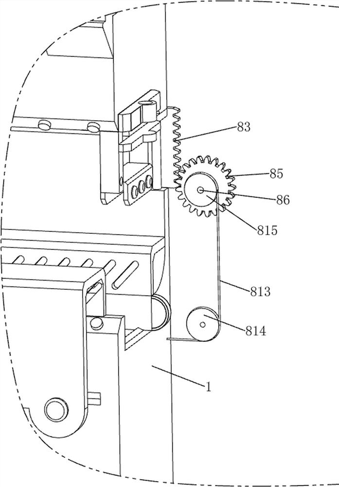
[0037] On the basis of Example 1, as figure 1 , figure 2 and Image 6 As shown, a collection mechanism 5 is also included. The collection mechanism 5 includes a mounting plate 51, a first motorized roller 52, a second motorized roller 53 and a collection frame 54. A collection frame 54 is placed on the right side of the card holder 2. The collection frame 54 uses For collecting soap, a mounting plate 51 is provided between the right side of the housing 1 and the left side of the collecting frame 54. The mounting plate 51 is inclined at a high left and a low right, so that the soap after being cut off slides to the right to the collecting frame 54. Before the mounting plate 51 There are 9 first electric rollers 52 connected evenly at the back of the mounting plate 51, the first electric rollers 52 are arranged in the direction of the right rear, and the rear part of the mounting plate 51 is evenly connected with three second electric rollers 53, the second electric rollers 5...


PUM


Abstract

The invention relates to section cutting equipment, in particular to uniform section cutting equipment for soap for production and processing. According to the soap uniform cutting equipment for production and processing, the cutter can be automatically lifted to cut soap into sections, and the working efficiency is improved. Soap uniform sectioning equipment for production and processing comprises a shell, a clamping seat, a cutting mechanism and the like, the clamping seat is arranged on the lower right side of the shell, the cutting mechanism is arranged on the shell and comprises a first fixing block, an electric push rod and a push frame, the first fixing block is arranged on the upper right side of the shell, and the electric push rod is arranged in the middle of the first fixing block; pushing frames are arranged at the bottoms of telescopic rods of the electric push rods. A telescopic rod of the electric push rod continuously stretches out and draws back, the tool rest and the cutter can be driven to continuously move up and down, and the cutter can cut off soap at intervals; and meanwhile, when the output shaft of the gear motor rotates, the conveying belt can rotate, so that the soap can be conveyed rightwards.

Description

technical field [0001] The invention relates to a segment cutting device, in particular to a uniform segment segmenting device for soap for production and processing. Background technique [0002] In the process of soap production, the soap needs to be shaped, cooled and formed first. Since the formed soap is relatively large, it is necessary to cut the soap into sections. The current method of cutting the soap is generally operated by special cutting equipment. [0003] The patent application number is CN201520613592.4 A soap dicing machine, including a conveyor belt and a cutting knife, and a plurality of cutting knives are fixedly installed on the conveyor belt. Ear nuts, springs and fixed laminates, a number of bolts are fixed on the upper end of the soap quick fixing box, the bolts are arranged through the spring and the fixed laminate, and the upper and lower ends of the spring are respectively fixed on the upper end of the soap bar fixing box and fixed The lower end ...

Claims


Application Information

Patent Timeline
IPC IPC(8): B26D1/06B26D5/08B26D7/06B26D7/32B26D7/26C11D13/22
CPCB26D1/06B26D5/086B26D7/0625B26D7/32B26D7/2614C11D13/22
Inventor 李彪
Owner 李彪
Why Eureka
Try Eureka