Equipment mold for special elevator parts and machining method

A technology for parts and elevators, which is applied to the equipment molds and processing fields of special elevator parts, can solve the problems of time-consuming operation, unfavorable assembly work efficiency, troublesome installation of screws, etc.

Active Publication Date: 2022-07-22
广西壮族自治区特种设备检验研究院
View PDF10 Cites 0 Cited by
  • Summary
  • Abstract
  • Description
  • Claims
  • Application Information

AI Technical Summary

Problems solved by technology

[0008] The purpose of the present invention is to provide an equipment mold and a processing method for special elevator parts, so as to solve the problem that the traditional assembly method of elevator guide shoes proposed in the background technology is time-consuming for unskilled workers, and the installation screws are relatively complicated. It is troublesome and time-consuming to adjust the position of the assembly and parts back and forth, which is not conducive to improving the efficiency of assembly operations

Method used


Image

  • Equipment mold for special elevator parts and machining method
  • Equipment mold for special elevator parts and machining method
  • Equipment mold for special elevator parts and machining method

Examples


Embodiment 1

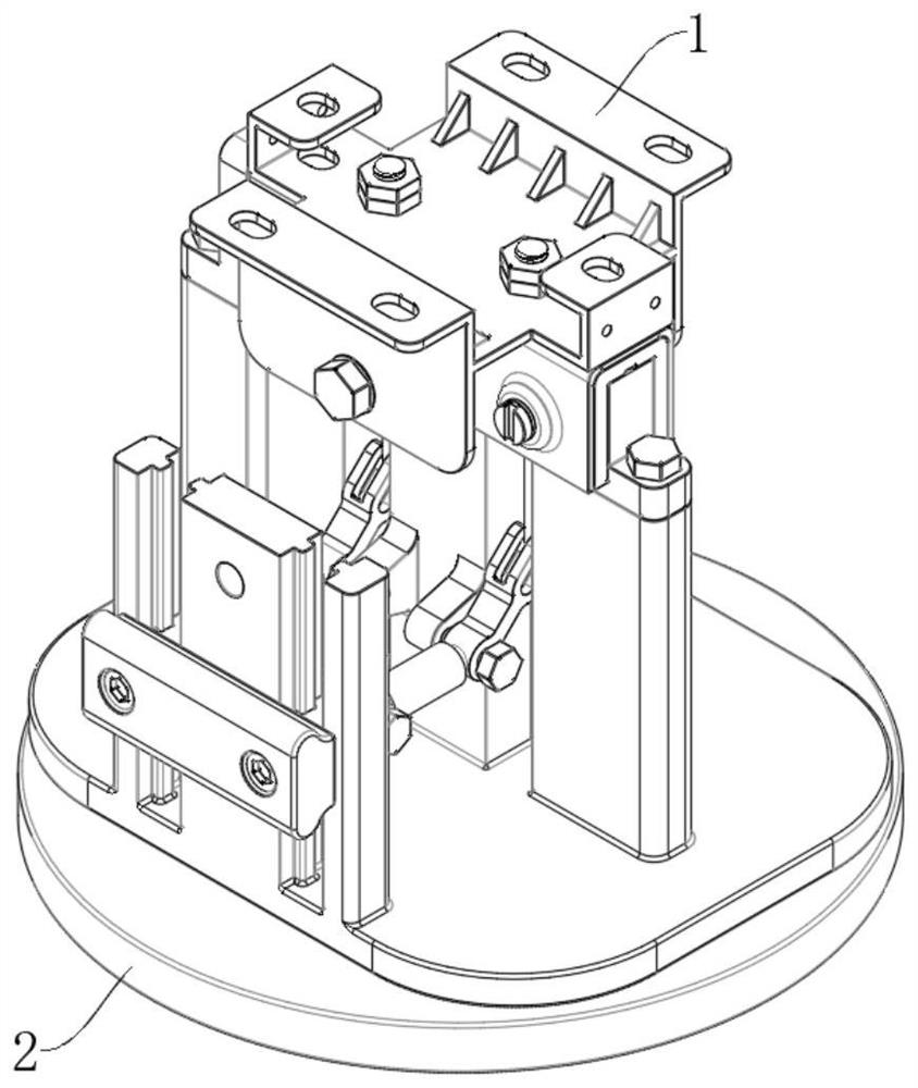
[0094] see figure 1 The present invention provides an equipment mold for special elevator parts, which includes an elevator guide shoe 1 as a special elevator part and a mold 2 used for assembling the elevator guide shoe 1 .

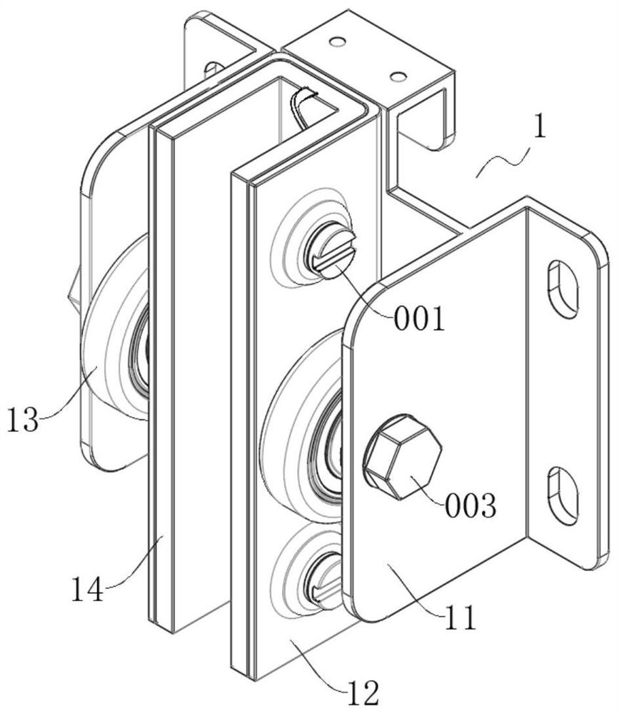
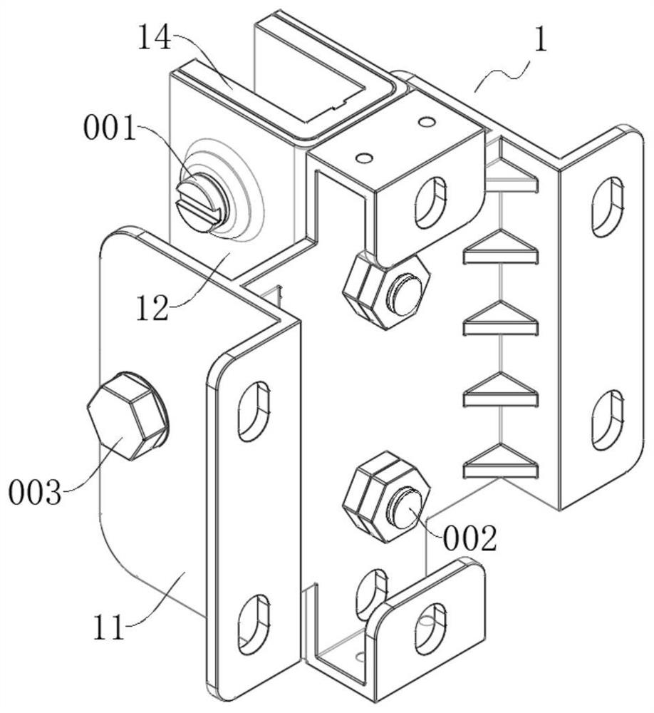
[0095] see figure 2 , image 3 and Figure 27 , The elevator guide shoe 1 provided by the present invention includes a shoe seat 11 , a shoe groove 12 , two guide wheels 13 and a shoe lining 14 . In addition, the elevator guide shoe 1 also includes four screws one 001 , two screws two 002 and two screws three 003 . Wherein, each screw 2002 is equipped with two matching nuts.

[0096] see Figure 4 and Figure 5 , the middle part of the shoe seat 11 provided by the present invention is a metal plate body in the shape of a square plate, and the upper and lower parts of the metal plate body are respectively provided with a hole 01 in the shape of a circular through hole. A 01 is arranged symmetrically up and down.

[0097] The upper and lower parts...

Embodiment 2

[0120] see Figure 28-Figure 32 , The present invention provides a processing method for the elevator guide shoe 1 to be assembled by the equipment mold of the special elevator parts.

[0121] S1. First, push the push rod body 410 upward by hand, so that the push rod 400 is pushed to the front of the upper slot one 205 in the second turntable stand 240 . At this time, the hole eighteen 406 is aligned with the groove one 205, the ball 430 is no longer blocked by the turntable stand 240, and the compressed spring 420 restores its own elasticity and pushes the ball 430 backward, so that the ball The rear ball of 430 is snapped into the inner cavity of the slot one 205 , so that the push rod 400 is limited in front of the slot one 205 .

[0122] In the present invention, when the push rod body 410 is pushed upward, the hinge seat 500 slides upward along the chute 204 under the driving action of the push rod 400, so that the hinge cylinder 600 moves upward, and the hinge cylinder ...


PUM


Abstract

The invention discloses an equipment mold for special elevator parts, and belongs to the technical field of elevator guide shoe assembly. Comprising a die used for assembling the elevator guide shoe, and the elevator guide shoe comprises a shoe seat, a shoe groove, a guide wheel and a shoe lining. The elevator guide shoe further comprises a first screw used for limiting the shoe guide in the shoe groove, a second screw used for installing the shoe groove and the shoe guide in front of the shoe base and a third screw used for installing the guide wheel in a clamping cavity formed between the shoe base and the shoe groove. When two parts are fixed through screws, a worker does not need to free one hand to stably hold the two parts, and when a new part is added on the basis of the combined body, the position of the combined body does not need to be adjusted again.

Description

technical field [0001] The invention relates to the technical field of elevator guide shoe assembly, in particular to an equipment mold and a processing method for special elevator parts. Background technique [0002] The elevator guide shoe is a part of the elevator, which is generally assembled from parts such as a shoe seat, a shoe groove, a shoe lining and a guide wheel. Therefore, the outline of the elevator guide shoe is not a regular square. [0003] At present, the assembly operation with the elevator guide shoe is generally performed manually. The common method is to place the various parts of the elevator guide shoe in different storage boxes according to their types, and then place these storage boxes containing the parts on the workbench, and workers will pick up the corresponding parts according to the assembly steps, and Assemble the picked parts together step by step on the table top of a flat workbench. This traditional assembly method has the following de...

Claims


Application Information

Patent Timeline
Patent Type & Authority Applications(China)
IPC IPC(8): B66B7/04
CPCB66B7/047
Inventor 严波
Owner 广西壮族自治区特种设备检验研究院
Why Eureka
Try Eureka