
Rotating support connecting piece of scaffold protective net

A technology of rotating brackets and protective nets, which is applied to the accessories of scaffolding, building structure supports, building structure supports, etc. It can solve the problems of affecting the safety of the construction base, the high pressure of the hinge shaft, and the easy deformation of the hinge shaft, so as to improve the installation efficiency. The effect of reducing stress and ensuring stability

Pending Publication Date: 2022-07-22
江苏云奇建筑机械有限公司
View PDF7 Cites 0 Cited by
  • Summary
  • Abstract
  • Description
  • Claims
  • Application Information

AI Technical Summary

Problems solved by technology

[0003] At present, in the installation process of the scaffolding protection net, corners are often encountered. At this time, the protection net needs to be rotated to meet the installation requirements of the construction site. At present, the rotation of the protection net is mostly through the hinge shaft. The two protective nets are connected, and then the two protective nets are rotated to achieve the purpose of rotating the two protective nets. However, this installation method puts a relatively large pressure on the hinge shaft, which will cause all the weight of the protective net to be pressed on the hinge shaft. In addition, the hinge shaft is easily deformed, and the two protective nets are in a rotatable state. Once the protective net at a certain position breaks in a strong wind, the protective net will automatically rotate with the wind, so that the position of the protective net will change. Shaking at any angle can easily cause the entire protective net to collapse, affecting the safety of the construction base

Method used


Image

  • Rotating support connecting piece of scaffold protective net
  • Rotating support connecting piece of scaffold protective net
  • Rotating support connecting piece of scaffold protective net

Examples


Embodiment Construction

[0018] In order to deepen the understanding of the present invention, the present invention will be described in further detail below with reference to the embodiments and the accompanying drawings. The embodiments are only used to explain the present invention and do not constitute a limitation on the protection scope of the present invention.

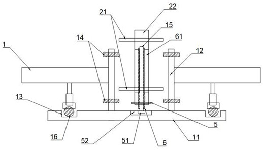
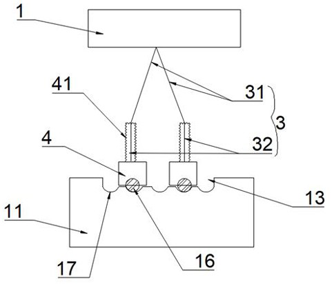
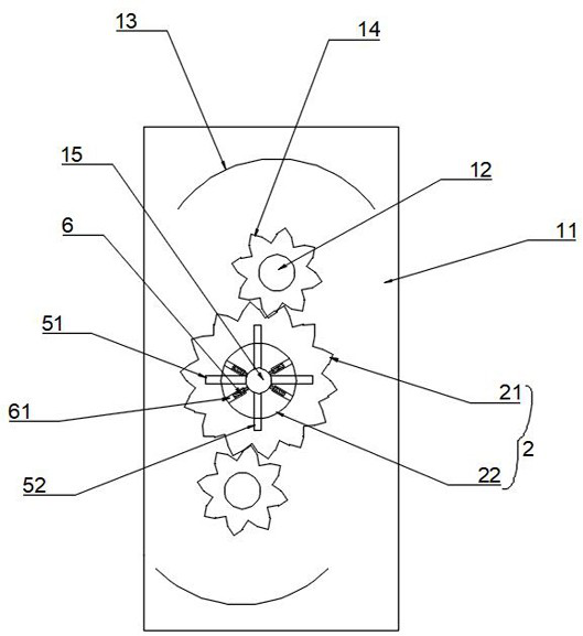
[0019] like Figure 1 to Figure 3 It is a specific embodiment of the present invention. Its structure includes two protective nets 1, and its structure also includes a base 11. The base 11 is provided with two rotatable support rods 12, and the two protective nets 1 are respectively connected one by one. On the support rod 12, the upper and lower sides of the protective net 1 and the upper and lower ends of the support rod 12 maintain a safe distance, respectively. The bottom of the protective net 1 is provided with a support 3, and the base 11 is provided with a track groove 13. The support 3 The rolling is arranged inside the track ...


PUM


Abstract

The rotating support connecting piece structurally comprises two protective nets and further structurally comprises a base, two rotatable supporting rods are arranged on the base, the two protective nets are connected to the supporting rods in a one-to-one mode, and safe distances are kept between the upper sides and the lower sides of the protective nets and the upper ends and the lower ends of the supporting rods correspondingly. Supporting pieces are arranged at the bottoms of the protective nets, track grooves are formed in the base, the supporting pieces are arranged in the track grooves in a rolling mode, outer gears are arranged at the upper ends and the lower ends of the supporting rods correspondingly, a fixing rod is arranged between the two supporting rods, limiting pieces for limiting rotation of the outer gears are arranged on the fixing rod, and a plurality of balls are arranged at the bottoms of the supporting pieces. And a plurality of arc-shaped grooves are distributed in the track groove and distributed along the track groove, the balls are matched with the arc-shaped grooves to limit the rotating position of the protective net, and the using safety performance of the scaffold protective net is ensured.

Description

Technical field: [0001] The invention relates to the technical field of production of scaffolding, in particular to a rotating bracket connecting piece of a scaffolding protective net. Background technique: [0002] Scaffolding is a working platform set up to ensure the smooth progress of each construction process. The scaffolding protective mesh is set on the outside of the scaffolding to protect the workers walking on the scaffolding or heavy objects from falling. [0003] At present, during the installation of the scaffolding protective net, corners are often encountered. At this time, the protective net needs to be rotated and installed to meet the installation requirements of the construction site. At present, most of the rotation of the protective net is through the hinge shaft. The two protective nets are connected, and then the two protective nets are rotated to achieve the purpose of rotating the two protective nets. Then this installation method has a relatively l...

Claims


Application Information

Patent Timeline
Patent Type & Authority Applications(China)
IPC IPC(8): E04G21/32E04G5/00
CPCE04G21/3266E04G21/3204E04G5/001
Inventor 陈建忠
Owner 江苏云奇建筑机械有限公司
Learn More