Large-range highway detection equipment

A technology for highways and testing equipment, applied in measurement devices, instruments, optical devices, etc., can solve the problems of affecting the detection value, the adjustment process cannot be carried out in real time, and the efficiency is low.

Pending Publication Date: 2022-07-22
王莉立
View PDF0 Cites 0 Cited by
  • Summary
  • Abstract
  • Description
  • Claims
  • Application Information

AI Technical Summary

Problems solved by technology

The existing road surface detection equipment detects the smoothness of the road surface by emitting multi-point collimated laser beams to the road surface, but the laser needs to be adjusted to cover the entire road surface under different road surface widths, and the adjustment process cannot be carried out in real time. low efficiency
And when the detection vehicle passes through the curve and the inclined road surface, the detection value will be affected by the change of the relative position between the detection device and the road surface.

Method used


Image

  • Large-range highway detection equipment
  • Large-range highway detection equipment

Examples


Embodiment Construction

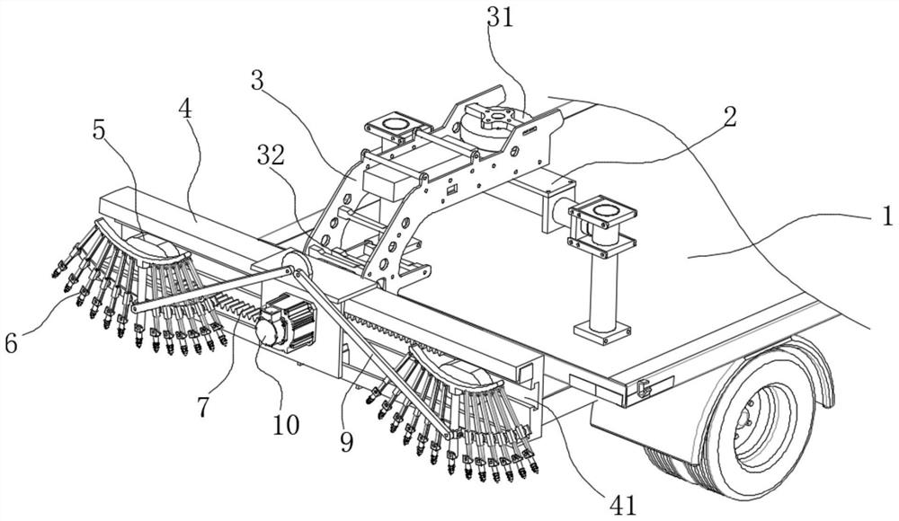
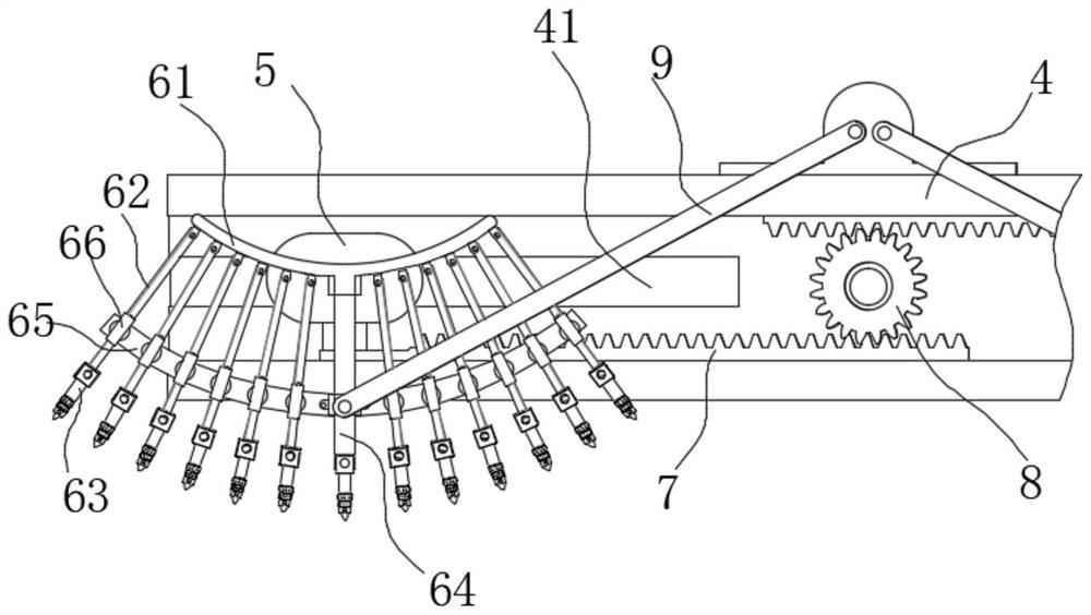
[0021] see figure 1 and figure 2 , In the embodiment of the present invention, a large-scale highway detection equipment includes a vehicle body 1, a bracket 2 is fixed at the rear of the vehicle body 1, and a balance frame 3 is connected to the bracket 2, and the balance frame 3 A cross bar 4 perpendicular to the traveling direction of the vehicle body 1 is connected to the cross bar 4 , and two detection assemblies 6 are symmetrically arranged on both sides of the cross bar 4 .

[0022] In this embodiment, the balance frame 3 is rotatably connected to the bracket 2 , and its rotation axis is perpendicular to the bottom surface of the vehicle body 1 , and it can be driven to rotate by a motor one 31 .

[0023] In this embodiment, the cross bar 4 is rotatably connected to the gimbal 3 , and its rotation axis is parallel to the traveling direction of the vehicle body 1 , and can be driven to rotate by the second motor 32 .

[0024] In this embodiment, a chute 41 is defined i...


PUM


Abstract

The invention discloses large-range highway detection equipment which comprises a vehicle body, a support is fixed to the rear portion of the vehicle body, a balance frame is connected to the support, a cross rod perpendicular to the advancing direction of the vehicle body is connected into the balance frame, two detection assemblies are symmetrically arranged on the two sides of the cross rod, and each detection assembly comprises a fixing plate. The fixing plate is an arc-shaped plate fixedly connected with the sliding block, a plurality of connecting rods are evenly distributed below the fixing plate, and laser sensors are fixed to the other ends of the connecting rods respectively. Compared with the prior art, the laser sensors distributed on the two sides of the transverse rod in the arc-shaped mode can conduct fan-shaped detection on the ground, and the road condition of the road surface can be dynamically detected by analyzing the distance change of each laser sensor.

Description

technical field [0001] The invention relates to the technical field of road surface detection, in particular to a large-scale highway detection device. Background technique [0002] The road inspection vehicle integrates and applies modern information technology, and integrates optoelectronics, IT and 3S technology with motor vehicles as a platform. In the normal driving state of the vehicle, it can automatically complete the data collection, analysis, classification and storage of road surface image, road surface shape, three-dimensional image of road facilities, smoothness and road geometric parameters. The existing pavement inspection equipment detects the smoothness of the pavement by emitting multi-point collimated laser beams to the pavement. However, the laser needs to be adjusted to cover the entire pavement under different pavement widths, and the adjustment process cannot be performed in real time. low efficiency. And the detection value will be affected by the r...

Claims


Application Information

Patent Timeline
IPC IPC(8): G01B11/30
CPCG01B11/30
Inventor 王莉立李恒张志荣缑庆辉朱延王震
Owner 王莉立
Why Eureka
Try Eureka