
Piezoelectric actuation micro-nano deflection platform

A piezoelectric actuation, micro-nano technology, applied in the direction of generators/motors, piezoelectric effect/electrostrictive or magnetostrictive motors, electrical components, etc., can solve the problem of improving the rotation stroke, reducing the driving stroke, and utilization No high-level problems, to achieve the effect of protection displacement amplification, not easy to lose stability and overturn, and relatively stable structure

Pending Publication Date: 2022-07-22
GUANGZHOU UNIVERSITY
View PDF1 Cites 0 Cited by
  • Summary
  • Abstract
  • Description
  • Claims
  • Application Information

AI Technical Summary

Problems solved by technology

There is an existing Chinese invention patent, authorized announcement number: CN103177774B. When the turntable realizes one degree of freedom rotation, the composition of the turntable has a displacement amplification mechanism and a fixed rotating hinge. In terms of space arrangement, the fixed hinge is on the central axis of the platform. The displacement amplification mechanism is distributed on both sides of the platform, and the two drivers push the platform to deflect. When one side is stacked, the stiffness of the other side itself has a restraining effect, which reduces the driving stroke, and the two drivers used cannot work at the same time, so the utilization rate is not good. High, and the supporting hinge separates the two drives, so that the turning radius is relatively large, and the structure is not compact enough, so it is generally difficult to greatly increase the turning stroke of this type of turning table stroke

Method used


Image

  • Piezoelectric actuation micro-nano deflection platform
  • Piezoelectric actuation micro-nano deflection platform
  • Piezoelectric actuation micro-nano deflection platform

Examples


Embodiment Construction

[0016] The technical solutions in the embodiments of the present invention will be clearly and completely described below with reference to the accompanying drawings in the embodiments of the present invention. Obviously, the described embodiments are only a part of the embodiments of the present invention, but not all of the embodiments. Based on the embodiments of the present invention, all other embodiments obtained by those of ordinary skill in the art without creative efforts shall fall within the protection scope of the present invention.

[0017] It should be noted that all directional indications (such as up, down, left, right, front, rear...) in the embodiments of the present invention are only used to explain the relative relationship between various components in a certain posture (as shown in the accompanying drawings). If the specific posture changes, the directional indication also changes accordingly.

[0018] In addition, descriptions such as "first", "second",...


PUM


Abstract

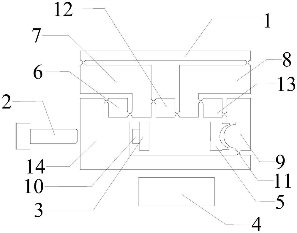
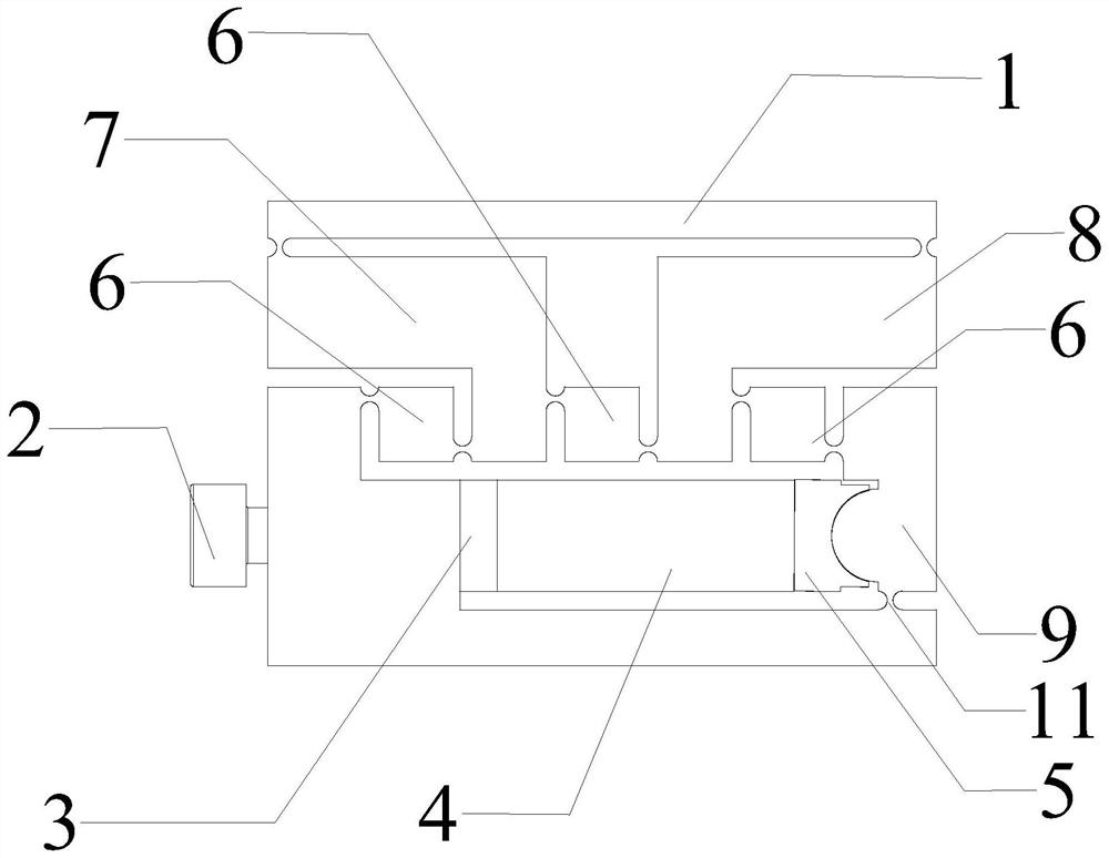
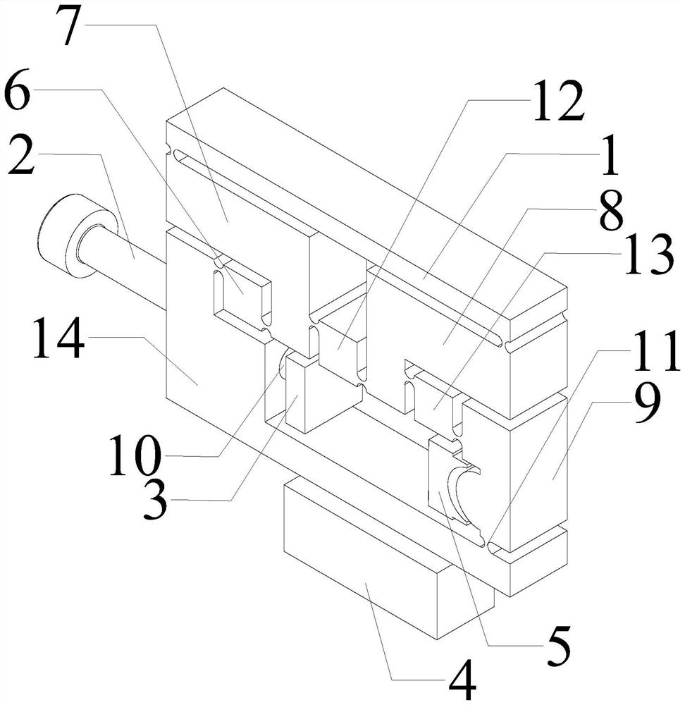
The piezoelectric actuation micro-nano deflection platform comprises a rotating table, L-shaped rods, a rotating block, a supporting column, a pre-tightening bolt, a T-shaped ejector block, a piezoelectric ceramic stack and a rotating cushion block, the rotating table is arranged above the two L-shaped rods, a guide rod is arranged on the T-shaped ejector block and slides in a positioning hole of the pre-tightening bolt of a base, the pre-tightening bolt is screwed into the base, and the rotating cushion block is arranged on the rotating table. And the piezoelectric ceramic stack is horizontally clamped between the guide rod and the rotating cushion block, and the rotating cushion block and the supporting column form a rotating pair. Compared with the prior art, one piezoelectric ceramic stack realizes the rotation effect driven by two traditional piezoelectric ceramic stacks, the use amount of the piezoelectric stacks is reduced, and the rotation stroke is increased. Platform deflection can be achieved without winding around a fixed hinge, the rotating shaft is arranged in the middle of the platform, and symmetry is good. The piezoelectric actuation flexible deflection mechanism can realize angular displacement amplification of the platform.

Description

technical field [0001] The invention relates to the field of mirror image stabilization, in particular to a piezoelectric actuated micro-nano deflection platform. Background technique [0002] Cameras are one of the important devices for acquiring image information in modern technology, and image quality is the most important performance indicator of cameras. Image stabilization is a key technology to improve image quality, and its essence is to suppress the impact of camera vibration on image quality. Camera vibration can be divided into linear vibration and angular vibration. The piezoelectric stabilization image utilizes the advantages of piezoelectric ceramic stacks such as fast dynamic response, high resolution, large driving force, small size, high rigidity and not being affected by magnetic fields. vibration effect. Angular vibration is the main factor affecting the imaging quality, so a high-performance rotational image stabilization platform is required to suppre...

Claims


Application Information

Patent Timeline
IPC IPC(8): H02N2/12
CPCH02N2/123
Inventor 黄卫清雷银锋安大伟陈明杨张意
Owner GUANGZHOU UNIVERSITY
Learn More