
Lifting structure, single wafer cleaning mechanism, method and equipment

A technology of lifting structure and cleaning mechanism

Pending Publication Date: 2022-07-29
创微微电子(常州)有限公司
View PDF0 Cites 1 Cited by
  • Summary
  • Abstract
  • Description
  • Claims
  • Application Information

AI Technical Summary

Problems solved by technology

[0003] The object of the present invention includes providing a lifting structure, which can improve the technical problem of poor lifting synchronization in the prior art

Method used


Image

  • Lifting structure, single wafer cleaning mechanism, method and equipment
  • Lifting structure, single wafer cleaning mechanism, method and equipment
  • Lifting structure, single wafer cleaning mechanism, method and equipment

Examples


Embodiment 1

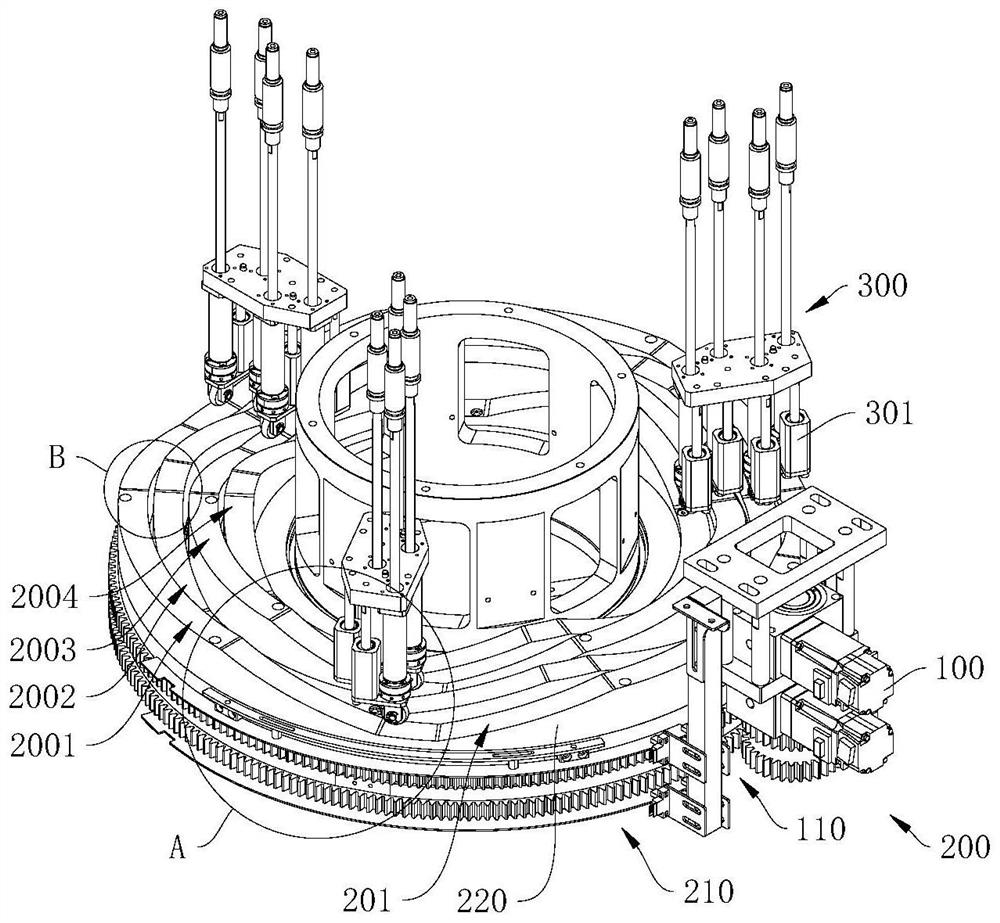
[0054] In order to improve the technical problem of poor lift synchronization in the prior art, a lift structure 13 is provided in this embodiment.

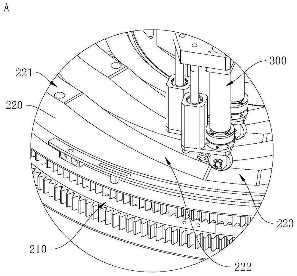
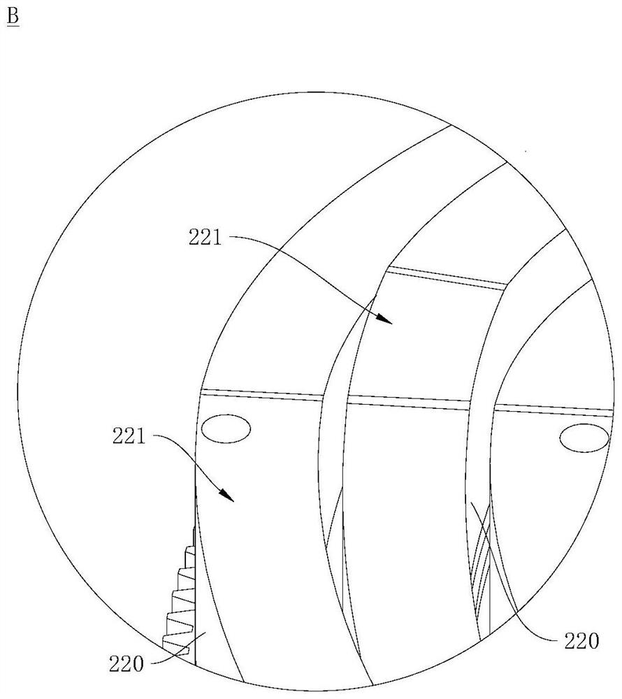
[0055] Among them, see figure 1 , figure 1 A schematic structural diagram of the lifting structure 13 provided in the embodiment of the present application is shown. The lift structure 13 includes a drive assembly 200 and at least one lift assembly 300 . The driving assembly 200 includes a driving part 210 and an abutting body 220 , and the abutting body 220 is connected with the driving part 210 . The top of the abutting body 220 has an abutting surface 201 , and the abutting surface 201 is undulating in a predetermined direction. In other words, the heights of the abutting body 220 at different positions relative to the driving part 210 vary. One end of the lift assembly 300 abuts against the abutment surface 201 , and when the driving part 210 drives the abutment body 220 to move in a predetermined direction, the lift asse...

Embodiment 2

[0091] see Figure 5 , Figure 5 A schematic structural diagram of the single-wafer cleaning mechanism 10 provided in this embodiment is shown. In this embodiment, a single-wafer cleaning mechanism 10 is provided. The single-wafer cleaning mechanism 10 is used to clean a single wafer to remove residues, fine dust, dirt, etc. on the single wafer, so as to ensure that the single wafer is cleaned. Wafers are of high quality. In the process of cleaning the single wafer, the single wafer cleaning mechanism 10 will spray a variety of chemicals on the single wafer to ensure that various residues on the single wafer can be effectively cleaned. Based on this, in order to prevent cross-contamination between multiple agents, in the process of cleaning a single wafer with each agent, the products generated after cleaning a single wafer with each agent need to be collected separately.

[0092] The single-wafer cleaning mechanism 10 has multiple covers 12, the multiple covers 12 are cove...

Embodiment 3

[0111] Based on the single-wafer cleaning mechanism 10 provided in the second embodiment, a single-wafer cleaning method is provided in this embodiment, and the method can be applied to any single-wafer cleaning mechanism 10 provided in the second embodiment. The wafer is cleaned to improve the technical problem of poor lift synchronization in the prior art.

[0112] Among them, in order to facilitate the execution of the single-wafer cleaning method, in this embodiment, the single-wafer cleaning mechanism 10 may further include a control device, the driving part 210 is electrically connected to the control device, and the control device can control the operation of the driving part 210 to control the Lifting and lowering of the plurality of covers 12 . The cleaning mechanism 15 is electrically connected to the control device, the control device can control the cleaning mechanism 15 to clean the wafer, and the cleaning mechanism 15 can also feed back a signal indicating that t...


PUM


Abstract

The invention provides a lifting structure, a single wafer cleaning mechanism, a single wafer cleaning method and single wafer cleaning equipment, and relates to the technical field of semiconductor processing equipment. The lifting structure comprises a driving assembly and at least one lifting assembly. The driving assembly comprises a driving part and at least one abutting body, and the abutting body is connected with the driving part; the top of the abutting body is provided with an abutting face, and the abutting face is in a fluctuating shape in the preset direction. One end of the lifting assembly abuts against the abutting face, and the driving part drives the abutting body to move in the preset direction so that the lifting assembly can move along the abutting face. The single wafer cleaning mechanism provided by the invention adopts the lifting structure and can execute the single wafer cleaning method provided by the invention; the single wafer cleaning mechanism is adopted in the single wafer cleaning equipment provided by the invention. According to the lifting structure, the single wafer cleaning mechanism, the single wafer cleaning method and the single wafer cleaning equipment provided by the invention, the technical problem of poor lifting synchronism in the prior art can be improved.

Description

technical field [0001] The present invention relates to the technical field of semiconductor processing equipment, and in particular, to a lifting structure, a single-wafer cleaning mechanism, method and equipment. Background technique [0002] In the semiconductor industry, a variety of chemical liquid processes are common in wafer wet cleaning equipment. Therefore, it is not only necessary to discharge multiple medicinal liquids separately, but also to separate the exhaust of each medicinal liquid to avoid mutual pollution among the medicinal liquids. There are a variety of cover lift methods in the industry today. Most of these method structures have poor lift synchronization, so that the air tightness between the covers is poor. SUMMARY OF THE INVENTION [0003] The purpose of the present invention includes providing a lifting structure, which can improve the technical problem of poor synchronization of lifting and lowering in the prior art. [0004] The purpose of ...

Claims


Application Information

Patent Timeline
Patent Type & Authority Applications(China)
IPC IPC(8): B08B11/00B08B3/02B08B11/02B08B13/00H01L21/67H01L21/687
CPCB08B11/00B08B11/02B08B3/022B08B13/00H01L21/6704H01L21/68742
Inventor 许峯嘉蔡嘉雄徐柏翔
Owner 创微微电子(常州)有限公司
Learn More