Hydraulic forging device for forging metal device

A metal device and hydraulic technology, applied in forging/pressing/hammer devices, driving devices of forging presses, and forging presses, etc., can solve the problems of not being able to fit the workpiece perfectly, hidden dangers, and ineffective limit forgings, etc. To achieve the effect of facilitating loading and unloading, reducing safety hazards and increasing usage scenarios

Pending Publication Date: 2022-07-29
杜文晓
View PDF1 Cites 0 Cited by
  • Summary
  • Abstract
  • Description
  • Claims
  • Application Information

AI Technical Summary

Problems solved by technology

[0004] However, when the device is in use, due to the plasticity of the forging, when the size and contour of the forging change with the continuous hammering of the forging, there will be a large gap betwee

Method used


Image

  • Hydraulic forging device for forging metal device
  • Hydraulic forging device for forging metal device
  • Hydraulic forging device for forging metal device

Examples


Example Embodiment

[0036] Example 1:

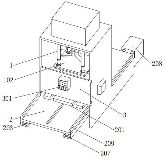
[0037] A hydraulic forging device for forging metal parts, comprising a frame 1, the frame 1 is a "冂"-shaped structure, the inner top of the frame 1 has four hydraulic cylinders 101 in a rectangular array, and the bottom of the hydraulic cylinder 101 is fixed An upper mold 102 is connected, a support table 2 is fixedly installed directly under the frame 1, a lower mold 201 is assembled on the top of the support table 2, the lower mold 201 is arranged in parallel with the upper mold 102, and a protective plate 3 is hinged on the front of the rack 1. , the front of the protective plate 3 is fixedly connected with the controller 301, and the height of the protective plate 3 is greater than the length of the working stroke of the hydraulic cylinder 101;

[0038] The forging device used for forging metal parts also includes: the support table 2 and the lower die 201 are rotatably connected through the rotating shaft 202, the front end of the lower die 201 is pro...

Example Embodiment

[0041] Example 2:

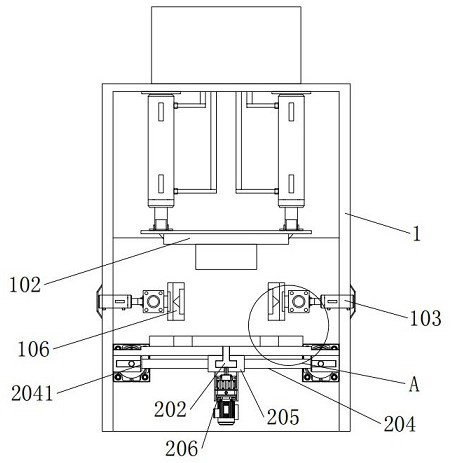
[0042] The difference between this embodiment and Embodiment 1 is that: the length of the support table 2 is three times the length of the frame 1, the frame 1 is nested in the outer middle position of the support table 2, and the inner center of the support table 2 is provided with a sliding grooves, slide rails 203 are installed on both sides of the bottom of the support table 2;

[0043] The openings of the slide rails 203 are arranged opposite to each other, and the interior of the slide rail 203 is embedded with a connecting column 204, and the opposite ends of the two connecting columns 204 are fixedly installed with a limit block 205, and the limit block 205 is sleeved on the outer side of the rotating shaft 202;

[0044] The rotating shaft 202 is in an inverted "T" shape, the bottom of the limit block 205 is fixedly connected with a servo motor one 206, and the output end of the servo motor one 206 is connected to the rotating shaft 202 by transmiss...


PUM


Abstract

The invention provides a hydraulic forging device for forging a metal device, which is characterized in that a support table is rotatably connected with a lower die through a rotating shaft, the front end of the lower die is provided with two grooves which are horizontally arranged in parallel, and the rear side of the top of the lower die is provided with a cuboid bulge; the design of the second hydraulic oil cylinder and the clamping block is adopted, the second hydraulic oil cylinder drives the rotating air cylinder, the connecting column and the clamping block to move, the two hydraulic oil cylinders located on the two sides work independently, the forge piece can be limited, clamped and fixed when the two hydraulic oil cylinders are matched with each other, and meanwhile the forge piece can be turned over conveniently through the design of the rotating air cylinder; and in the process that the hydraulic oil cylinder II drives the clamping block to clamp the forge piece to move horizontally, the position of the forge piece is adjusted more flexibly, the position change and the overall dimension change of the forge piece can be adapted, the forge piece is limited stably all the time, potential safety hazards are reduced, and using is more convenient and faster.

Description

technical field [0001] The invention relates to the technical field of mechanical manufacturing, in particular to a hydraulic forging device for forging metal parts. Background technique [0002] Forging equipment is a kind of mechanical equipment that uses hydraulic oil as the working medium. By hammering the metal material in a plastic state, the physical and mechanical properties of the metal material are changed. Multiple hammer heads can deform the forgings to a certain extent through high-frequency beating, thereby changing the size and contour of the forgings. However, during the beating process, workers need to use clamps and other fixtures to continuously adjust the position of the forgings so that the forgings can be evenly distributed. However, manual adjustment of forgings is dangerous and depends on the proficiency of workers; [0003] For production safety, some automated hydraulic forging devices have been designed and manufactured. For example, a hydraulic f...

Claims


Application Information

Patent Timeline
IPC IPC(8): B21J9/02B21J9/12B21J13/04B21J13/02B21J13/10F16P1/02
CPCB21J9/02B21J9/12B21J13/04B21J13/02B21J13/10F16P1/02
Inventor 杜文晓
Owner 杜文晓
Why Eureka
Try Eureka