

Carton packaging and transporting device
A technology for transportation devices and cartons, applied in packaging, packaging protection, transportation and packaging, etc., can solve the problems of easy misalignment of materials, high labor intensity, increased labor intensity, etc., and achieve the effect of improving packaging efficiency
- Summary
- Abstract
- Description
- Claims
- Application Information
AI Technical Summary
Problems solved by technology
Method used
Image

Examples
Embodiment 1
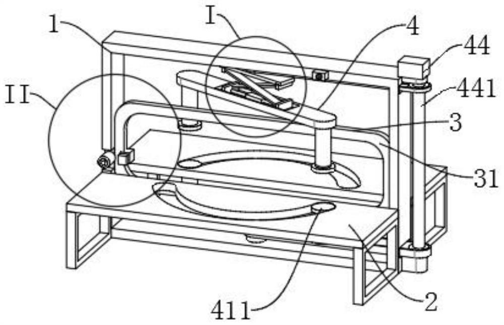
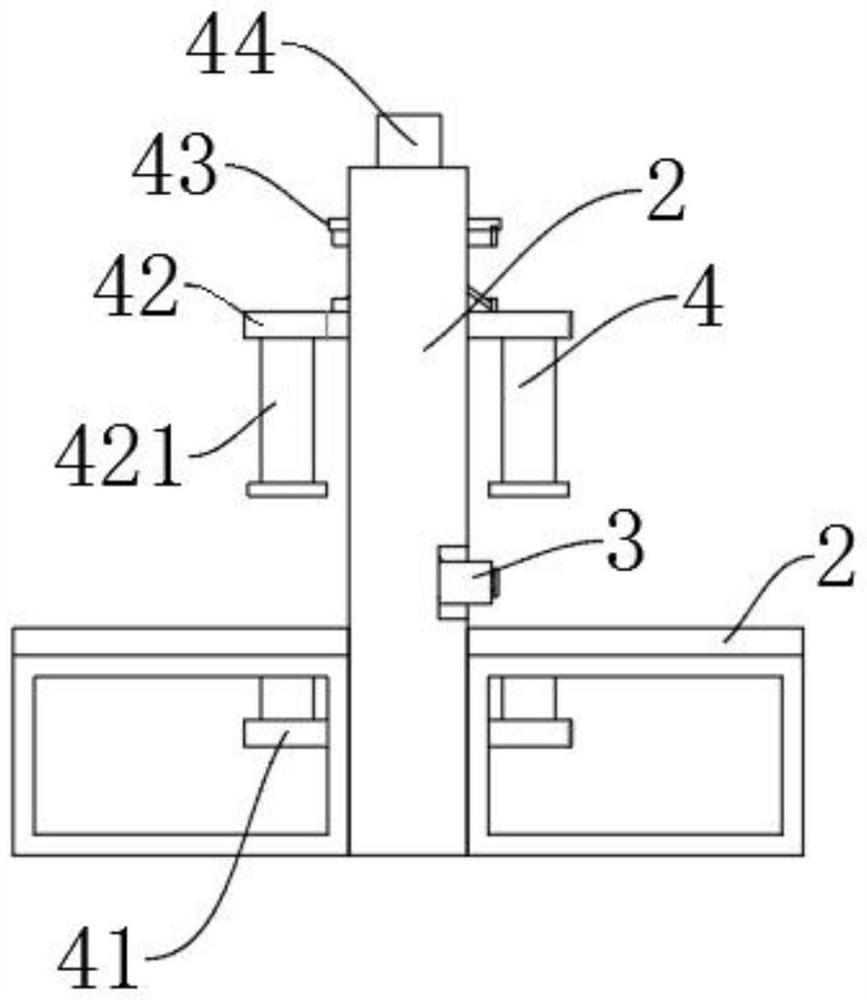
[0034] Example one, as Figure 1-5 As shown in the figure, a carton packaging and transporting device includes a vertically arranged die frame 1, a workbench 2 is provided on both front and rear sides of the die holder 1, and a packaging mechanism 3 for bundling materials is provided on the inner side of the die frame 1 , Specifically, the packaging mechanism 3 is located in the gap between the two worktables 2, and the die frame 1 is also provided with a clamping and rotating mechanism 4 for clamping the material and enabling the material to rotate 90 degrees in the horizontal plane, Specifically, the included angle between the vertical plane where the packing mechanism 3 is located and the vertical plane where the clamping and rotating mechanism 4 is located is an acute angle, and the angle of the acute angle is 30-60 degrees, preferably 30 degrees. Correspondingly located on the upper side of workbench 2, it will not affect the feeding work;
[0035] The clamping and rotat...
Embodiment 2
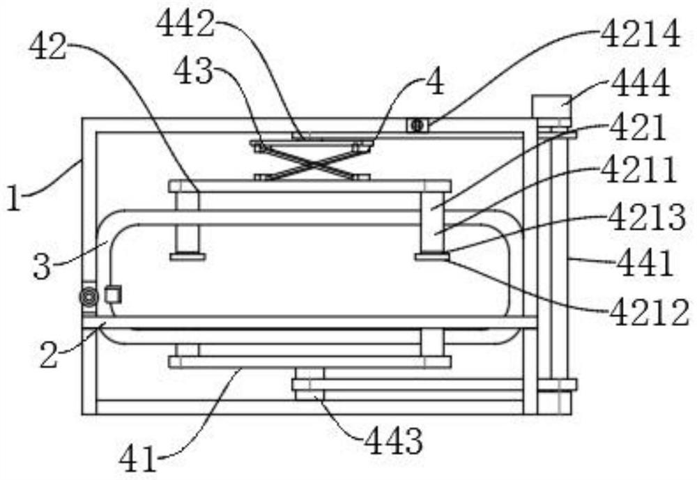
[0039] Embodiment 2, on the basis of Embodiment 1, as Figure 4 As shown, the first driving mechanism 43 includes a horizontal slide rail 431 , two first sliding blocks 432 are arranged at the bottom of the horizontal sliding rail 431 along the axial direction, and the first sliding blocks 432 are axially slidably fitted to the horizontal sliding rail 431 . In the horizontal slide rail 431, a connecting rod 433 is hinged at the bottom of each first sliding block 432, and the two connecting rods 433 are in a cross structure, and the middle parts of the two connecting rods 433 are connected by pins, and the lower ends of the connecting rods 433 are hinged with a second connecting rod 433. Two sliding blocks 434, and the second sliding block 434 is axially slidably fitted to the upper horizontal beam 42 along the horizontal slide rail 431;
[0040] The first driving mechanism 43 further includes a driving device 435 capable of driving the two first sliding blocks 432 or the two s...
Embodiment 3
[0044] Embodiment 3, on the basis of embodiment 2, as Figure 1-2 As shown, the second driving mechanism 44 includes a transmission shaft 441, a first rotating shaft 442, and a second rotating shaft 443. The transmission shaft 441 is arranged vertically and is connected to the die frame 1 through a bearing seat. The die frame 1 is provided with a The drive motor 444 that the transmission shaft 441 rotates and cooperates with; the first rotating shaft 442 is vertically arranged, and the lower end is correspondingly fixed to the middle of the top surface of the horizontal slide rail 431, and the upper end of the first rotating shaft 442 is rotatably connected to the die frame 1; the second The rotating shaft 443 is arranged vertically, and the upper end is correspondingly fixed to the lower horizontal beam 41, and the lower end of the second rotating shaft 443 is rotatably connected to the die frame 1, and the second rotating shaft 443 is coaxially arranged with the first rotatin...
PUM
 Abstract
Description
Claims
Application Information