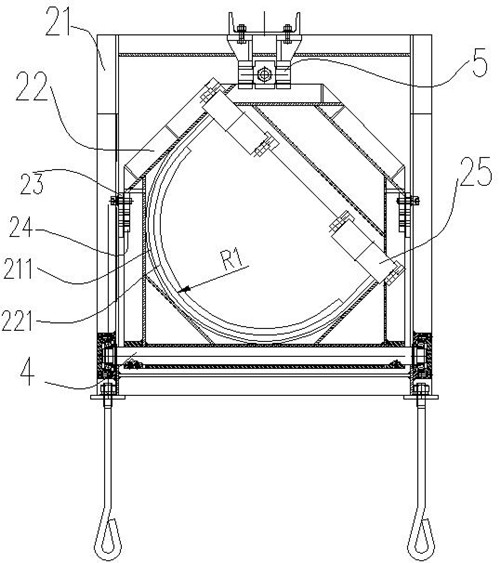
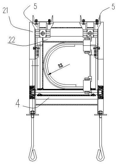
Belt turning mechanism, belt conveyor comprising belt turning mechanism and belt turning method of belt conveyor

A technology for turning belts and tapes, which is applied in the direction of conveyors, conveyor objects, transportation and packaging, etc. It can solve the problems of unfavorable space use and space occupation in limited space, reduce the impact of rigid deformation, improve service life, and protect tapes Effect

Pending Publication Date: 2022-07-29
TAIAN ENDLESS MECHANICAL & ELECTRICAL TECH CO LTD
View PDF7 Cites 0 Cited by
  • Summary
  • Abstract
  • Description
  • Claims
  • Application Information

AI Technical Summary

Problems solved by technology

[0003] At present, there are the following types of belt turning devices: pinch roller type, vertical belt turning type, semi-circular tube type, etc., but there are some disadvantages, such as the pinch roller type and vertical direction turning belt type, the turning height of which is higher than the length of the belt itself. It is not conducive to the use of venues with limited space; CN203558422U discloses a belt turning device for a circular tube belt conveyor, which consists of two sets of lower parallel idler rollers and two sets of upper parallel idlers independently installed on a fixed intermediate frame or frame. The roller group and three sets of hexagonal idler roller groups are composed to complete the belt turning
However, in order to eliminate the excessive deformation of the belt edge caused by excessive restraint during the belt turning process, a longer belt turning distance is required to offset the belt edge deformation caused by being restrained, so as to reduce the belt edge stress and wear the conveyor belt Reach the normal state, so take up a lot of space

Method used


Image

  • Belt turning mechanism, belt conveyor comprising belt turning mechanism and belt turning method of belt conveyor
  • Belt turning mechanism, belt conveyor comprising belt turning mechanism and belt turning method of belt conveyor
  • Belt turning mechanism, belt conveyor comprising belt turning mechanism and belt turning method of belt conveyor

Examples


Embodiment Construction

[0032] The present invention will be further described in detail below in conjunction with the embodiments. The advantages and features of the present invention will become apparent as the description proceeds. However, these examples are only exemplary and do not constitute any limitation to the scope of the present invention. It should be understood by those skilled in the art that the details and forms of the technical solutions of the present invention can be modified or replaced without departing from the spirit and scope of the present invention, but these modifications and replacements all fall within the protection scope of the present invention.

[0033] Words such as "comprising" and "comprising" indicate that in addition to the components that are directly and explicitly stated in the specification and claims, the technical solution of the present invention does not exclude other components that are not directly or explicitly stated. situation. In the description ...


PUM


Abstract

The invention provides a belt turning mechanism, a belt conveyor comprising the belt turning mechanism and a belt turning method of the belt conveyor, the belt conveyor comprises a first belt pressing roller set, a plurality of belt turning devices and a second belt pressing roller set which are arranged in sequence in the running direction of a rubber belt, and each turning device is provided with a belt turning restraining assembly. And the adhesive tape turning section is turned over by 180 degrees through the tape turning device in a segmented mode, and then adhesive tape turning is completed. Therefore, the use occasions of the belt turning device are increased, and the abrasion of the belt turning device to the belt is reduced.

Description

technical field [0001] The invention relates to the field of conveyors, in particular to a belt turning mechanism, a belt conveyor including the same and a belt turning method thereof. Background technique [0002] Belt conveyors, also known as belt conveyors, are widely used in mining, metallurgy, electric power, ports and other industries. For long-distance conveyors, after the belt conveyor unloads the material, the bearing surface of the conveyor belt will adhere to the part. Residual material, on the one hand, the residual material will stick to the lower roller, which will not only increase the wear of the roller skin, increase the operating burden of the conveyor, cause the belt to deviate, and at the same time cause the material to be scattered along the way, polluting the transportation route. After the belt conveyor unloads the material, the tape is turned over, so that the tape bearing surface of the return section turns to the upper part, which can solve the prob...

Claims


Application Information

Patent Timeline
Patent Type & Authority Applications(China)
IPC IPC(8): B65G15/32B65G15/62B65G39/06
CPCB65G15/32B65G15/62B65G39/06
Inventor 周满山张媛孙斌武刘超武楠
Owner TAIAN ENDLESS MECHANICAL & ELECTRICAL TECH CO LTD
Why Eureka
Try Eureka