Rapid construction vibration leveling device based on municipal road engineering
A municipal road and engineering technology, which is applied in the field of rapid construction vibrating devices, can solve the problems of increasing labor burden, reducing smoothing efficiency, reducing vibration effect, etc., and achieves the effects of reducing labor burden, improving smoothing efficiency, and improving vibration effect
- Summary
- Abstract
- Description
- Claims
- Application Information
AI Technical Summary
Problems solved by technology
Method used
Image
Examples
Embodiment 1
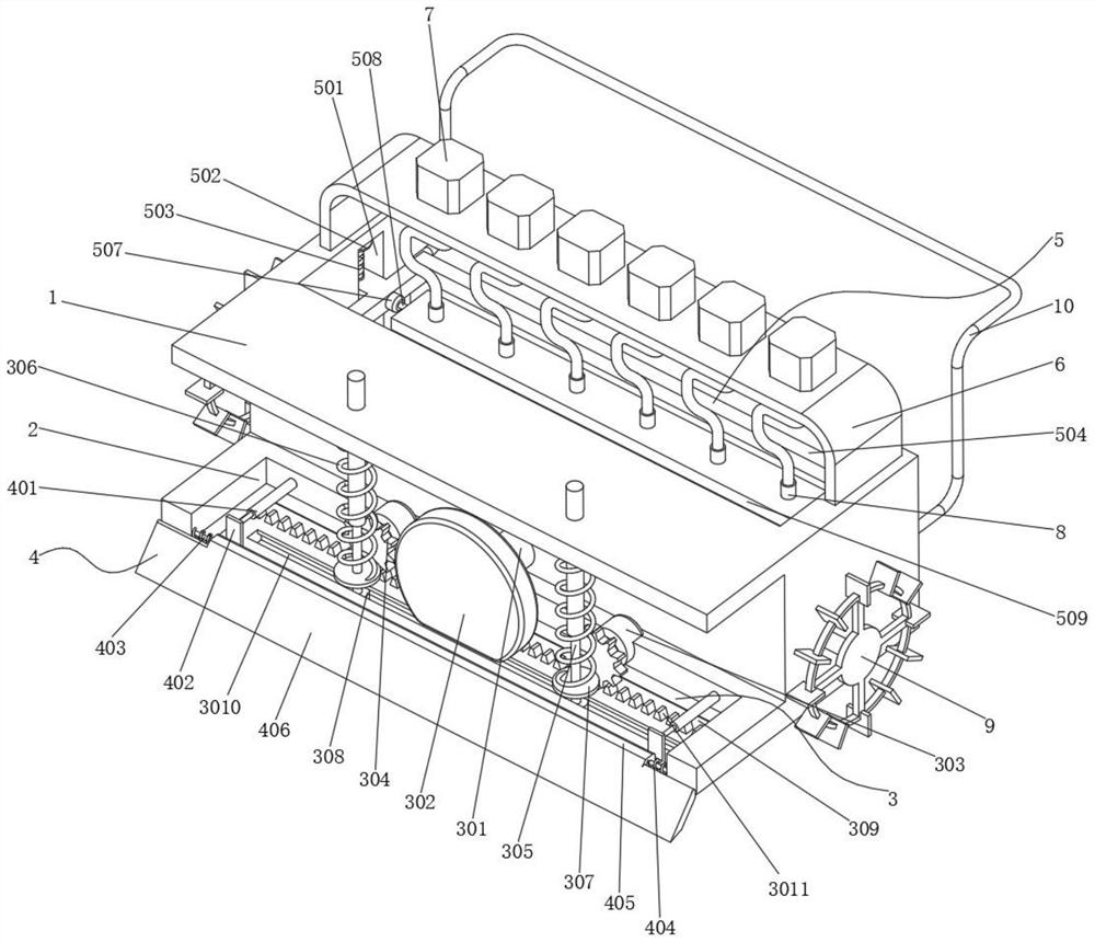
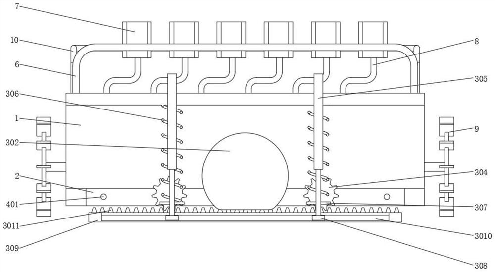
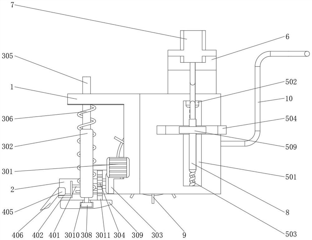
[0027] see Figure 2-3 , the present invention provides a technical solution: a rapid construction leveling device based on municipal road engineering, comprising a mounting frame main body 1, a first lifting groove 2, a leveling component 3, a troweling component 4 and an adjusting component 5, the mounting frame A first lifting groove 2 is opened on the inner wall of the bottom end of the main body 1 , a leveling component 3 is fixed on the inner wall between the first lifting groove 2 and the mounting frame main body 1 , and a leveling assembly 3 is fixed on one side outer wall of the mounting frame main body 1 . Component 4, an adjustment component 5 is fixed on the other side outer wall of the mounting frame main body 1; a bracket 6 is welded and fixed on the top outer wall of the mounting frame main body 1, and a vibrator 7 is distributed and installed on the top inner wall of the bracket 6, and the vibrator 7 A vibrating rod 8 is installed on the outer wall of the botto...
Embodiment 2
[0031] see figure 1 , the troweling assembly 4 includes a cylinder 401, a supporting plate 402, a first rotating shaft 403, a second spring 404, a rotating square rod 405 and a troweling plate 406, a troweling plate 406 is installed on one side outer wall of the main body 1 of the mounting frame, and the troweling plate 406 A rotating square rod 405 is welded and fixed on one side outer wall of the rotating square rod 405, a first rotating shaft 403 is welded on both outer walls of the rotating square rod 405, and the other end of the first rotating shaft 403 is rotatably connected to the inner wall of the first lifting groove 2, A second spring 404 is welded on both inner walls of the first lifting groove 2, and the other end of the second spring 404 is welded on the outer wall of the rotating square rod 405. A support plate 402 is symmetrically installed on one outer wall of the trowel plate 406. A cylinder 401 is inlaid and installed on the inner wall of one side of the fir...
Embodiment 3
[0034] see Figure 4-5 , the adjusting assembly 5 includes a second lifting groove 501, a third motor 502, a threaded rod 503, a frame 504, a slider 505, a threaded hole 506, a fourth motor 507, a second rotating shaft 508 and an adjusting plate 509. A frame 504 is installed on the inner wall of one side, and sliders 505 are welded on the outer walls of both sides of the frame 504. The inner walls of the mounting frame 1 are provided with a second lifting slot 501 corresponding to the sliders 505 on both sides of the inner wall. The second lifting slot 501 A third motor 502 is inlaid and installed on the inner wall of the top end, a threaded rod 503 is rotatably connected to the inner wall of the bottom end of the second lifting groove 501, and the bottom end of the output shaft of the third motor 502 is fixedly connected to the outer wall of the threaded rod 503, sliding A threaded hole 506 is formed on the inner wall of one side of the block 505 corresponding to the threaded...
PUM
 Abstract
Description
Claims
Application Information
 - R&D
- Intellectual Property
- Life Sciences
- Materials
- Tech Scout
- Unparalleled Data Quality
- Higher Quality Content
- 60% Fewer Hallucinations
Browse by: Latest US Patents, China's latest patents, Technical Efficacy Thesaurus, Application Domain, Technology Topic, Popular Technical Reports.
© 2025 PatSnap. All rights reserved.Legal|Privacy policy|Modern Slavery Act Transparency Statement|Sitemap|About US| Contact US: help@patsnap.com


