Expanded-base prestressed composite anchor cable uplift pile, preparation method and equipment

A technology of prestressed and uplift piles, which is applied in the direction of sheet pile walls, buildings, and foundation structure engineering, and can solve the problems of discounting the bearing capacity of piles, affecting the quality of uplift piles, and being unable to further improve the anti-floating capacity of uplift piles, etc. , to achieve the effect of guaranteeing the use effect

Pending Publication Date: 2022-07-29
北京京投交通枢纽投资有限公司 +1
View PDF1 Cites 0 Cited by
  • Summary
  • Abstract
  • Description
  • Claims
  • Application Information

AI Technical Summary

Problems solved by technology

[0004] 1. Although the bearing capacity of the uplift pile can be improved by setting the shovel in the comparison document, when the pile is put into the drilled vertical hole, the outer side of the shovel will be in close contact with the inner wall of the vertical hole , which will make the shovels unable to fully unfold and provide resistance to the pile body when the pile body is subjected to an upward force, which will greatly reduce the bearing capacity of the pile body;
[0005] 2. The bottom of the pile body in the comparison document is not equipped with any structure to improve its anti-floating ability. It is very limited to improve the anti-floating ability of the pile body only by setting shovels, and it is impossible to further improve the overall anti-floating ability of the uplift pile;
[0006] 3. At the same time, after placing the reinforcement cage used for the production of the current uplift pile in the vertical hole, if it is necessary to adjust the position of the reinforcement cage in the hole, a large crane is required to lift it, and it is difficult for the driver of the large crane to lift it. Precise control of the position of the reinforcement cage may affect the quality of the uplift pile after casting

Method used


Image

  • Expanded-base prestressed composite anchor cable uplift pile, preparation method and equipment
  • Expanded-base prestressed composite anchor cable uplift pile, preparation method and equipment
  • Expanded-base prestressed composite anchor cable uplift pile, preparation method and equipment

Examples


preparation example Construction

[0049] Further, the preparation method of the bottom-expanded prestressed composite anchor cable uplift pile, the method steps are as follows:

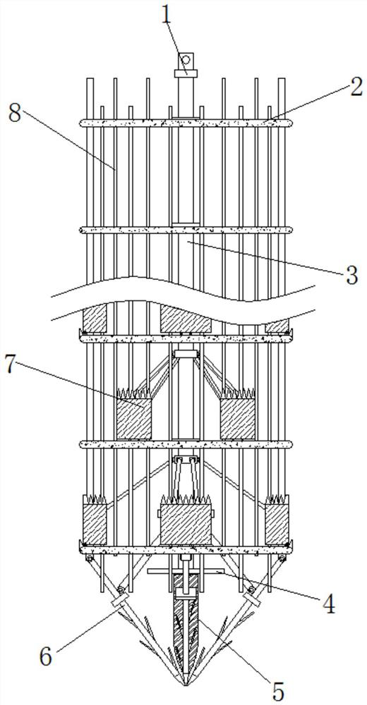
[0050] 1. First, place the uplift pile reinforcement cage composed of circular steel bars 2, straight steel bars and prestressed steel strands 8 into the pre-drilled holes on the ground through a crane;

[0051] 2. Then move the anti-pull pile preparation equipment to the outside of the hole, so that the outlet of the hole is located under the middle of the preparation equipment, then insert the I-beam 22 under the top group of circular steel bars 2, and put the I-beam The two ends of 22 are placed on the top of the U-shaped movable plate 17, so as to suspend the uplift pile reinforcement cage in the hole;

[0052] 3. Then, the output shaft of the gearbox 21 is fixedly connected with the connector 1 at the top of the main rod 3, and the second hydraulic cylinder 24 is controlled to rise, so that the bottom end of the insertion rod 6 i...

Embodiment 1

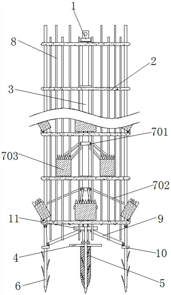
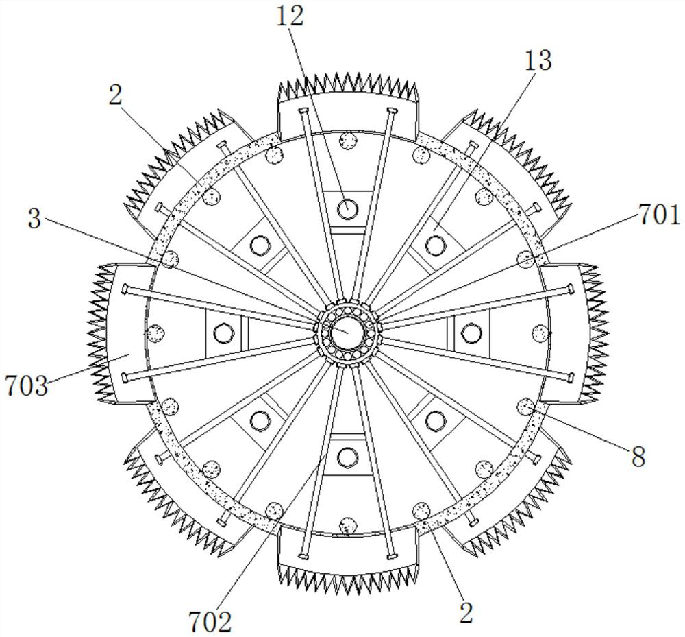
[0056] Example 1, as Figure 1-10 As shown, when the main rod 3 is slowly descending, through the cooperation of the hinge rod 9, the four groups of insertion rods 6 are forced to be gradually unfolded, until the insertion rods 6 are vertically positioned in the holes like the straight steel bars and the prestressed steel strands 8, Then, the driving motor 20 is controlled to cooperate with the gearbox 21 to drive the main rod 3 to rotate, forcing the drill bit 5 to gradually drill into the inner bottom of the hole. down, and the four sets of insert rods 6 will also be drilled into the inner bottom of the hole together with the drill bit 5, and the circular plate 4 is tightly pressed against the inner bottom of the hole, and then a plurality of auxiliary steel bars 12 are inserted vertically into each set of limit positions. Inside the slot 13, until the bottom end of the auxiliary steel bar 12 touches the inner bottom of the hole, and then extends into the inner bottom of the...

Embodiment 2

[0057] Example 2, as Figure 6-9 As shown, when the second hydraulic cylinder 24 is raised, the U-shaped movable plate 17 is raised together with the first hydraulic cylinder 18, the I-beam 22 and the top plate 19, the second lifting and shrinking rod 23 is stretched, and the top plate 19 When rising, the drive motor 20 and the gearbox 21 also rise together. Since the I-beam 22 supports a group of circular steel bars 2 on the top, when the U-shaped movable plate 17 rises, it will also rise together with the pull-resistant pile steel cage, When the first hydraulic cylinder 18 is shortened, the position of the reinforcement cage of the pullout pile remains unchanged, and the top plate 19 descends together with the drive motor 20 and the gearbox 21 , thereby descending with the main rod 3 .


PUM


Abstract

The invention discloses an expanded-base prestressed composite anchor cable uplift pile and a preparation method and equipment, the expanded-base prestressed composite anchor cable uplift pile comprises a main rod, the outer side of the main rod is uniformly sleeved with lantern rings, connecting rods are uniformly mounted on the outer sides of the lantern rings, and round steel bars are jointly mounted at the ends, away from the lantern rings, of the connecting rods; straight steel bars and prestressed steel strands are jointly and evenly installed on the inner sides of the multiple sets of round steel bars. After an uplift pile reinforcement cage is placed in a hole in the ground, the positions of round steel bars and straight steel bars are fixed, a main rod is controlled to descend, four sets of first telescopic rods gradually push away adjacent arc-shaped baffles after being shortened by a certain length, and when the arc-shaped baffles are unfolded, bottom expanding equipment of the arc-shaped baffles is extruded outwards to form a bottom expanding reinforcement cage; the pile body at the bottom expanding part is filled with the arc-shaped baffles, so that the arc-shaped baffles can be better attached to the pile body to reinforce the expanding head to enable the expanding head to have enough strength, and the expanding head stably provides upward resistance for the whole uplift pile. And pre-stress post-tensioning is conducted after construction is completed.

Description

technical field [0001] The invention relates to the technical field of construction engineering, in particular to a bottom-expanded prestressed composite anchor cable uplift pile, a preparation method and equipment. Background technique [0002] Anti-uplift piles are widely used in large-scale basement anti-floating, high-rise building anti-uplift, offshore dock platform uplift, suspension bridge and cable-stayed bridge anchor pile foundation, large dock floor pile foundation and static load test pile anchor pile foundation, etc. , The main mechanism of the anti-uplift pile is to rely on the friction between the pile body and the soil layer to resist the axial tension, such as anchor piles and anti-floating piles. [0003] The patent of the comparative document authorization announcement number CN108374413B discloses an uplift pile and its manufacturing method. In this patent, an openable shovel is arranged on the outer side wall of the pile to improve the bearing capacity o...

Claims


Application Information

Patent Timeline
Patent Type & Authority Applications(China)
IPC IPC(8): E02D5/58E02D31/12E02D5/36
CPCE02D5/58E02D31/12E02D5/36
Inventor 魏怡毛宗原王建军毛刚江楚雄姚松凯
Owner 北京京投交通枢纽投资有限公司
Why Eureka
Try Eureka