Belt air compressor with efficient heat dissipation function

An air compressor and belt technology, applied in mechanical equipment, machine/engine, dispersed particle separation, etc., can solve the problems affecting the normal operation of the belt air compressor and the large heat of the belt air compressor, so as to facilitate the collection and cleaning, improve the Heat dissipation function, the effect of avoiding damage

Pending Publication Date: 2022-07-29
沈兰均
View PDF4 Cites 0 Cited by
  • Summary
  • Abstract
  • Description
  • Claims
  • Application Information

AI Technical Summary

Problems solved by technology

[0005] In order to overcome the disadvantages that when people use most of the existing belt air compressors with heat dissipation function, relatively large heat is easily emitted around the belt air compressor, which will affect the normal operation of the belt air compressor. Belt air compressor with efficient heat dissipation function

Method used


Image

  • Belt air compressor with efficient heat dissipation function
  • Belt air compressor with efficient heat dissipation function
  • Belt air compressor with efficient heat dissipation function

Examples


Embodiment 1

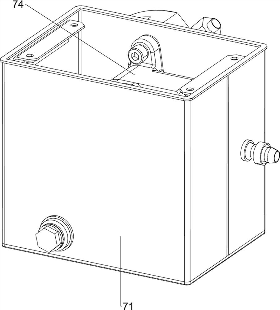
[0038] A belt air compressor with efficient heat dissipation, including a base 1, a fixed frame 2, a gasoline engine 3, a transmission mechanism 4, a blowing mechanism 5, a material storage mechanism 6 and a cooling mechanism 7, see Figure 1-Figure 11 As shown in the figure, the number of bases 1 is four, a fixed frame 2 is welded between the top of the base 1, and a gasoline engine 3 is bolted on the left side of the lower part of the fixed frame 2. The gasoline engine 3 is turned on to provide the belt air compressor with efficient heat dissipation. To provide power, the lower part of the fixing frame 2 is provided with a transmission mechanism 4; Institution 7.

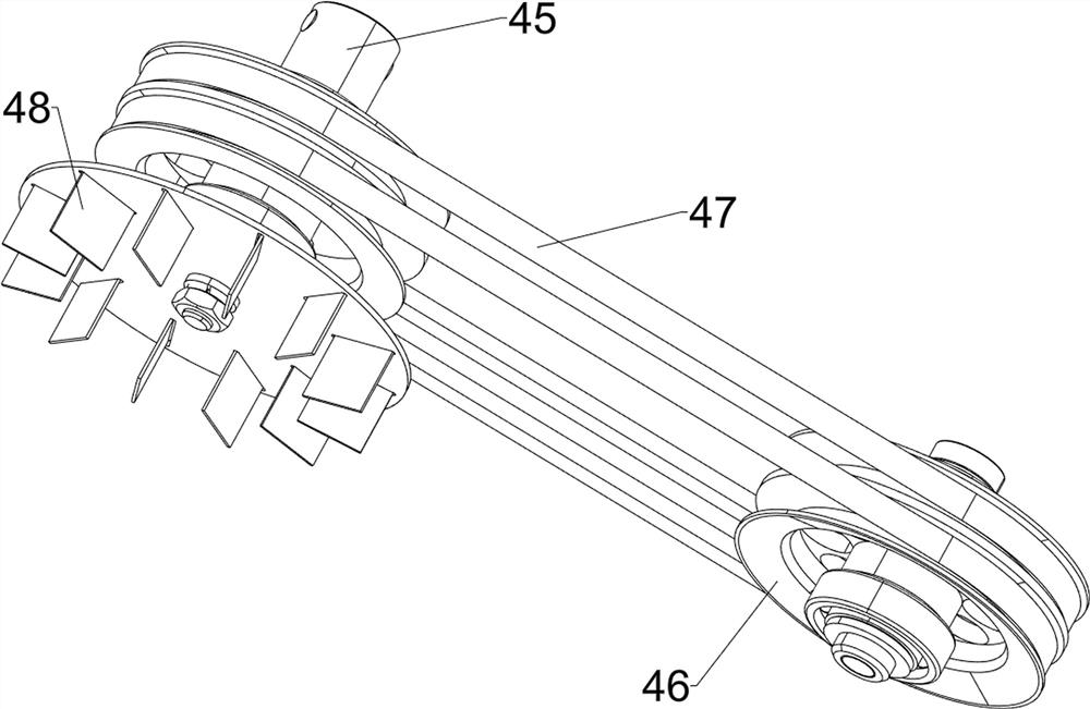
[0039] The transmission mechanism 4 includes a first mounting frame 41, a second mounting frame 42, a cover plate 43, an outer cover 44, a rotating rod 45, a transmission wheel 46, a belt 47 and an impeller 48, see figure 2 , image 3 and Figure 4As shown in the figure, a first mounting bracket 41 is welded o...

Embodiment 2

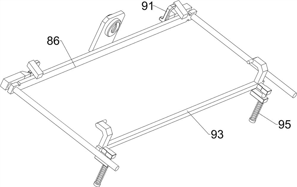
[0045] On the basis of Embodiment 1, a heat dissipation mechanism 8 is also included. The heat dissipation mechanism 8 includes a first connecting plate 81 , a heat dissipation fin 82 , a fan 83 , a filter screen 84 , a motor 85 , a first scraper 86 and a screw rod 87 . , see figure 1 and Figure 12 As shown, a first connecting plate 81 is welded on the lower right front of the fixing frame 2, the third conduit 72 passes through the upper part of the first connecting plate 81, the upper right side of the first connecting plate 81 is provided with a cooling fin 82, and the third conduit 72 Passing through the heat sink 82, fans 83 are bolted on both the front and rear sides of the upper inner side of the first connecting plate 81. When the fans 83 are turned on, the third duct 72 can be blown, thereby cooling the water in the third duct 72. The upper left side of the first connecting plate 81 is provided with a filter screen 84, the top left middle of the first connecting plat...


PUM


Abstract

The invention relates to a belt air compressor, in particular to a belt air compressor with an efficient heat dissipation function. The invention aims to provide the belt air compressor with the efficient heat dissipation function, which can absorb heat. The belt air compressor with the efficient heat dissipation function comprises at least two bases, a fixing frame, a gasoline engine and the like, the fixing frame is arranged between the tops of the bases, and the gasoline engine used for providing power is arranged on the left side of the lower portion of the fixing frame. A rotating shaft of a gasoline engine drives a rotating shaft of a water pump to rotate, so that the water pump starts to work, clear water circulates among a water tank, the water pump and a third guide pipe, and then the clear water in the third guide pipe can absorb heat near the belt air compressor with the efficient heat dissipation function; and therefore, the belt air compressor with the efficient heat dissipation function is cooled, and the heat dissipation function of the belt air compressor with the efficient heat dissipation function is improved.

Description

technical field [0001] The invention relates to a belt air compressor, in particular to a belt air compressor with a high-efficiency heat dissipation function. Background technique [0002] When rock drills, air picks and other equipment are used, an air compressor needs to be used to provide air source power. As a device for compressing gas, an air compressor will generate a certain amount of heat during use. In order to prevent the temperature from continuing to be too high If the equipment is damaged, it is necessary to carry out heat dissipation treatment on the air compressor. At present, in the use of the belt air compressor, the fan is often used as a radiator for heat dissipation treatment, so that the fan works to blow out the air to dissipate heat from the air compressor. Reduce the temperature of the air compressor to make the air compressor operate normally, but the wind blown by the fan cannot accurately cool the working parts in the air compressor, so the cooli...

Claims


Application Information

Patent Timeline
Patent Type & Authority Applications(China)
IPC IPC(8): F04B35/00F04B41/02F04B39/06F04D25/08F04D25/16F04D29/70B01D46/681B01D46/48B01D46/10
CPCF04B35/002F04B41/02F04B39/06F04B39/066F04D25/08F04D25/166F04D29/703B01D46/681B01D46/48B01D46/10
Inventor 沈兰均
Owner 沈兰均
Why Eureka
Try Eureka