
Eureka
For R&D, Eureka makes reading and utilizing patents & technical documents easy.
Eureka AIR
Designed for self-driven R&D workflows. Generate viable solutions, solve complex R&D challenges, empower your innovation with AI.

Eureka Materials
Designed for material experts only. Revolutionize your material R&D, from search, analyze, to developing new materials.

TechResearch
Generate reliable direction feasibility study reports for your R&D in just a few steps.

TechSeek
Discover and master advanced knowledge NOW. Basics, ideas, possibilities, all at once.

TechMind
As an expert in R&D Theories, TechMind can generates customized viable solutions instantly.

TechRisk
Analyze your overall solution with one click, know your potential R&D risks in advance.

TechMonitor
Get weekly tech updates, stay abreast of the latest tech innovations and key insights.
Path planning method and device, electronic equipment and storage medium
A route planning and driving route technology, applied in the direction of navigation calculation tools, etc., can solve the problems of large differences in the number of inspection points, time delay, waste of resources, etc., and achieve the effect of improving power utilization and inspection efficiency
- Summary
- Abstract
- Description
- Claims
- Application Information
AI Technical Summary
Problems solved by technology
Method used
Image

Examples
Embodiment 1
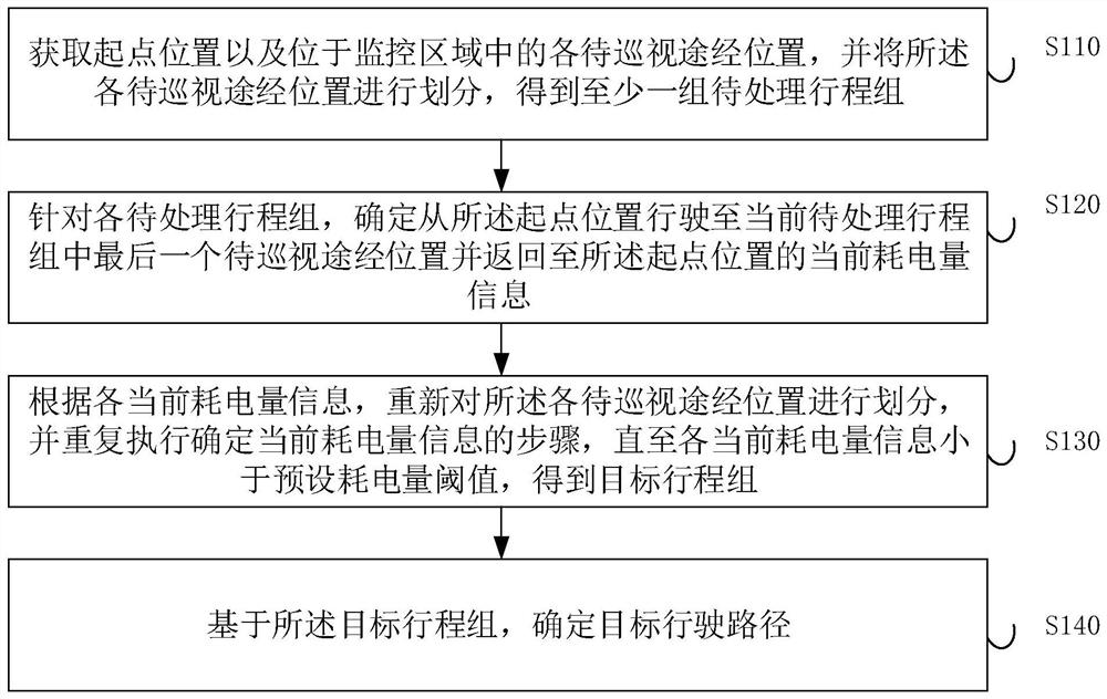
[0030] figure 1 This is a flowchart of a path planning method provided in Embodiment 1 of the present invention. This embodiment is applicable to the case of dividing tasks. The method can be executed by the path planning apparatus in this embodiment of the present invention, and the apparatus can use software and It is implemented by means of hardware, and optionally, it is implemented by an electronic device, and the electronic device may be a mobile terminal, a PC terminal, a server terminal, or the like. The apparatus may be configured in a computing device, and the path planning method provided in this embodiment specifically includes the following steps:
[0031] S110: Acquire the starting point position and each passing position to be patrolled in the monitoring area, and divide the each passing position to be patrolled into at least one group of to-be-processed itineraries.
[0032] Among them, the monitoring area can be understood as the area that needs to be routed,...
Embodiment 2
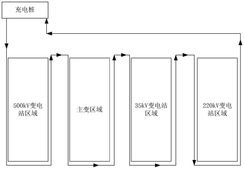
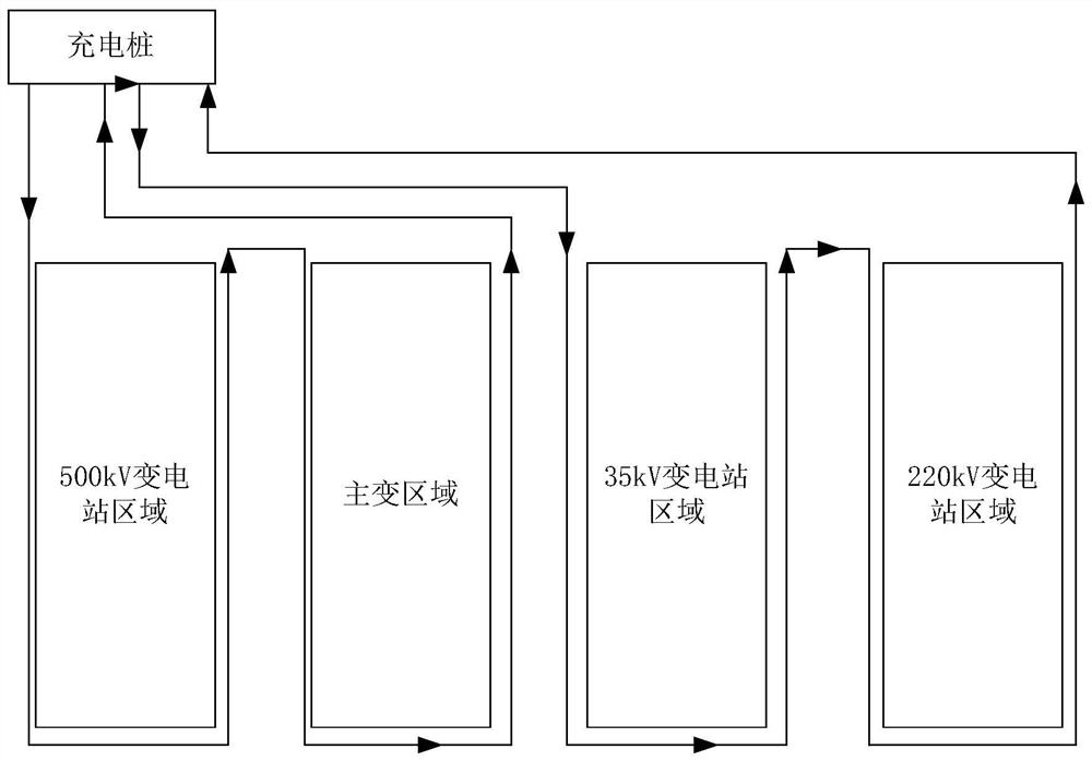
[0061] As an optional embodiment of the foregoing embodiment, in order to further clarify the technical solutions of the embodiments of the present invention to those skilled in the art, a specific application scenario example is given. Specifically, please refer to the following specific content.
[0062] see figure 2 , the monitoring area includes the 500kV substation area, the main substation area, the 35kV substation area and the 220kV substation area. The charging pile can be used as the starting position. At this time, the information on the number of groups to be updated is 1, and the driving path is to patrol the 500kV substation from the starting position. Each location to be inspected (substation equipment) in the area, and then arrive at the main substation area for inspection, patrol the 35kV substation area and the substation equipment in the 220kV substation area in turn, and then return to the starting position, assuming that the preset power consumption thresh...
Embodiment 3
[0066] Figure 5 This is a structural block diagram of a path planning apparatus provided by Embodiment 3 of the present invention. The device includes: a location division module 510 , a current power consumption information determination module 520 , a target travel group determination module 530 and a target travel path determination module 540
[0067] Wherein, the position division module 510 is used to obtain the starting point position and the passing positions to be patrolled in the monitoring area, and divide the passing positions to be patrolled to obtain at least one set of itinerary groups to be processed; wherein, the starting point The location corresponds to the charging pile, and the location to be patrolled corresponds to the substation equipment; the current power consumption information determination module 520 is used to determine, for each to-be-processed itinerary group, travel from the starting point to the current to-be-processed itinerary group The cu...
PUM
 Abstract
Description
Claims
Application Information
 - R&D Engineer
- R&D Manager
- IP Professional
- Industry Leading Data Capabilities
- Powerful AI technology
- Patent DNA Extraction
Browse by: Latest US Patents, China's latest patents, Technical Efficacy Thesaurus, Application Domain, Technology Topic, Popular Technical Reports.
© 2024 PatSnap. All rights reserved.Legal|Privacy policy|Modern Slavery Act Transparency Statement|Sitemap|About US| Contact US: help@patsnap.com