Chromatographic liquid phase sampling valve

A sampling valve and liquid phase technology, which is applied in the direction of instruments, measuring devices, scientific instruments, etc., can solve the problems of frequent replacement of sampling needles, cumbersome steps of replacing sampling needles, heavy workload of sampling needle replacement, etc., to achieve convenient maintenance Effects of replacement, improvement of vaporization capacity, and reduction of absorption

Pending Publication Date: 2022-07-29
BEIJING KALOON ANALYTICAL INSTR
View PDF9 Cites 0 Cited by
  • Summary
  • Abstract
  • Description
  • Claims
  • Application Information

AI Technical Summary

Problems solved by technology

[0004] After multiple samplings, the sampling needle will inevitably be worn, corroded or partially formed into solids. In order to ensure the accuracy of the subsequent liquid phase sampling volume, the sampling needle needs to be replaced in time; when replacing the sampling needle, it is necessary to remove the sampling needle from the piston rod. To dismantle it, in this process, the flange connection between the cylinder body and the liquid phase support needs to be removed first, and then th

Method used


Image

  • Chromatographic liquid phase sampling valve
  • Chromatographic liquid phase sampling valve
  • Chromatographic liquid phase sampling valve

Examples


Example Embodiment

[0037] Example 1:

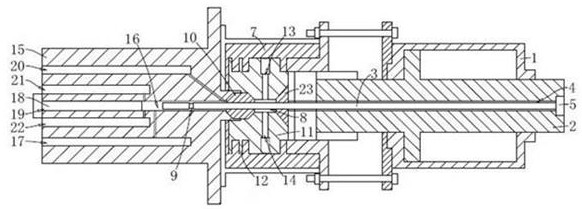
[0038] refer to figure 1 , the present application provides a chromatographic liquid sampling valve, comprising a cylinder 1, a piston rod 2 adapted to the cylinder 1, a sampling needle 3 fixed on the piston rod 2, a liquid The phase support 7, and the heating and gasification module arranged on the side of the liquid phase support 7 away from the cylinder 1, the liquid phase support 7 has a liquid phase chamber 8 for accommodating a liquid phase sample, and the heating and gasification module is There is a vaporization chamber 16 for vaporizing liquid-phase samples, the sampling needle 3 penetrates the liquid-phase chamber 8 and is inserted into the inside of the vaporization chamber 16, and pushes the piston rod 2 to make the sampling needle 3 continuously penetrate into the vaporization chamber 16 , the sampling needle 3 can then take a quantitative liquid phase sample into the gasification chamber 16 .

[0039]In order to facilitate the disassembly an...

Example Embodiment

[0052] Embodiment 2:

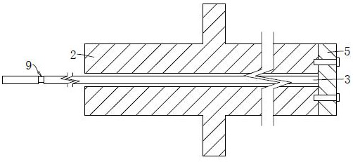
[0053] refer to figure 2 The difference between this embodiment and the first embodiment is that a connecting block 5 is fixed at the end of the sampling needle 3 , and the connecting block 5 is attached to the end surface of the piston rod 2 and is fixedly connected with the piston rod 2 by screws.

Example Embodiment

[0054] Embodiment three:

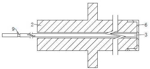
[0055] refer to image 3 , the difference between this embodiment and the first embodiment is that the connection mode between the sampling needle 3 and the piston rod 2 is different; in this embodiment, the connection mode between the sampling needle 3 and the piston rod 2 is different; In the embodiment, the end of the sampling needle 3 is fixed with a connection cover 6 that can be sleeved on the end of the piston rod 2 , and the connection cover 6 is threadedly connected with the piston rod 2 .


PUM


Abstract

The invention relates to the technical field of sample detection, in particular to a chromatographic liquid phase sampling valve which is characterized by comprising a cylinder body, a piston rod and a sampling needle, the piston rod penetrates through the two ends of the cylinder body and is in sliding connection with the cylinder body, and a needle hole allowing the sampling needle to be inserted is formed in the piston rod; one end of the sampling needle is detachably and fixedly connected with the corresponding end of the piston rod, and the other end of the sampling needle extends out of the piston rod; the purpose of reducing the workload of dismounting and replacing the sampling needle by conveniently dismounting and replacing the sampling needle is achieved.

Description

technical field [0001] The present application relates to the technical field of sample detection, in particular to a chromatographic liquid sampling valve. Background technique [0002] When a gas chromatograph detects a liquid sample, it needs to vaporize the liquid sample first, and then inject the vaporized sample, that is, the gas sample, into the chromatographic column, and analyze the sample through analytical instruments such as a detector; take a certain amount of The process of gasifying and vaporizing the liquid sample is often carried out using a chromatographic liquid sampling valve. [0003] A common chromatographic liquid sampling valve includes a cylinder body, a piston rod, a liquid phase support, and a heating and gasification module located on the side of the liquid phase support away from the cylinder body. A flange is passed between the cylinder body and the liquid phase support. Fixed connection, the piston rod runs through the cylinder body and one en...

Claims


Application Information

Patent Timeline
IPC IPC(8): G01N30/02G01N30/06G01N30/20
CPCG01N30/02G01N30/06G01N30/20
Inventor 冯维斌马韶尉王建涛邓冰
Owner BEIJING KALOON ANALYTICAL INSTR
Why Eureka
Try Eureka