Spring needle mounting and positioning structure for chip testing equipment

A chip testing, installation and positioning technology, applied in measuring devices, parts of electrical measuring instruments, measuring electricity, etc., can solve problems such as short-circuit links, blockages, increase the complexity of the pogo pin welding process, and reduce production conditions. , avoid positioning problems, improve the effect of consistency

Pending Publication Date: 2022-07-29
SHANGHAI AEROSPACE SCI & IND ELECTRIC APPLIANCE RES INST +1
View PDF0 Cites 0 Cited by
  • Summary
  • Abstract
  • Description
  • Claims
  • Application Information

AI Technical Summary

Problems solved by technology

The pogo pin welding must not be skewed because the head of the pogo pin touches the disc (PCB board), there are many pads, and the allowable position error is very small. If the position error of the pogo pin is large, it cannot correspond to the pads on the docking disc one by one. , it is easy to cause short circuit and link failure
As a result, the entire test system cannot work normally, which requires that the position control of the pogo pin welding on the PCB board is very precise, and precise automation equipment must be used, which also increases the complexity of the pogo pin welding process

Method used


Image

  • Spring needle mounting and positioning structure for chip testing equipment
  • Spring needle mounting and positioning structure for chip testing equipment
  • Spring needle mounting and positioning structure for chip testing equipment

Examples


Embodiment 1

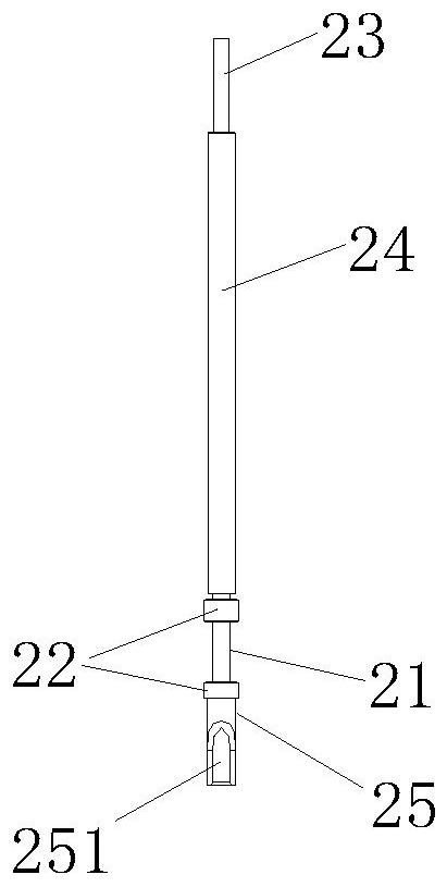
[0040] Example 1, attached figure 1It is a schematic structural diagram of the pogo pin 2 in the patented structure of the present invention, which consists of four parts, a tail structure 25, a sleeve 24, a probe head 23 and a spring (not shown in the figure), and the spring is installed inside the sleeve 24. , in contact with the bottom of the probe head 23; the tail structure 25 and the sleeve 24 are connected together by a round riveting point; the spring is loaded into the sleeve 24 and can be freely compressed in the sleeve 24; the head of the probe head 23 It is relatively thin, protrudes from the outside of the sleeve 24, and the bottom is thicker. It is installed inside the sleeve 24. The bottom of the probe head 23 is in contact with the spring, and the connection between the thickness of the probe head 23 forms a step. When the mouth is closed, the crimped edge is pressed on the step of the probe head 23, so that the probe head 23 is enclosed in the sleeve 24, and t...


PUM


Abstract

The invention discloses a spring needle mounting and positioning structure for chip testing equipment, and the structure comprises a pedestal which is provided with an assembly hole and a positioning hole, and the assembly hole is communicated with the positioning hole; the spring needle is arranged in the assembly hole in a penetrating manner, a positioning part is arranged on the spring needle, the positioning part is located at the communication position of the assembly hole and the positioning hole, and positioning steps are arranged at the positions, at the two ends of the positioning part, of the spring needle; the positioning piece and the positioning hole are the same in shape and size, a clamping hole is formed in the positioning piece, the cross section of the clamping hole and the cross section of the positioning part are the same in shape and size, the positioning piece is inserted into the positioning hole, and the positioning part is arranged in the clamping hole in a penetrating mode. The two ends of the positioning piece abut against the positioning steps at the external positions of the two ends of the positioning part respectively. According to the invention, the assembling process problem and the size guarantee problem of the spring needle are well solved. The method is simple and reliable, and the problems of welding and positioning of complex equipment are solved. And the production conditions are reduced. And meanwhile, the consistency of finished products is improved, and application and popularization conditions are met.

Description

technical field [0001] The invention relates to the technical field of chip testing equipment, in particular to a pogo pin mounting and positioning structure for chip testing equipment. Background technique [0002] In order to catch up with the level of the international chip industry, strengthen the country's scientific and technological strength, enhance the self-sufficiency of domestic chips, and meet the needs of various domestic industries for chips, various industries related to chips are now vigorously developing. Chip testing equipment is one of the necessary equipment. Due to the limitation of foreign technology, domestic chip testing equipment has just started, and imitation development is underway. [0003] The disc (PCB board) and the probe seat are mutually matched, and the low-frequency cable assembly and the high-frequency cable assembly are installed on the probe seat. The needle is in contact with the Pad on the PCB board of the disc, and various chips are...

Claims


Application Information

Patent Timeline
Patent Type & Authority Applications(China)
IPC IPC(8): G01R1/067
CPCG01R1/06722
Inventor 王宏吉许其峰李雍祎张蕾杜如民刘浩何远超
Owner SHANGHAI AEROSPACE SCI & IND ELECTRIC APPLIANCE RES INST
Why Eureka
Try Eureka