Laser projection equipment

A technology of laser projection and equipment, applied in the field of projection display, can solve the problems of large size of laser projection equipment, and achieve the effect of small size and compact arrangement

Pending Publication Date: 2022-07-29
QINGDAO HISENSE LASER DISPLAY CO LTD
View PDF0 Cites 0 Cited by
  • Summary
  • Abstract
  • Description
  • Claims
  • Application Information

AI Technical Summary

Problems solved by technology

[0004] However, the current laser projection equipment contains more optic

Method used


Image

  • Laser projection equipment
  • Laser projection equipment
  • Laser projection equipment

Examples


Example Embodiment

[0023] In order to make the objectives, technical solutions and advantages of the present application clearer, the embodiments of the present application will be further described in detail below with reference to the accompanying drawings.

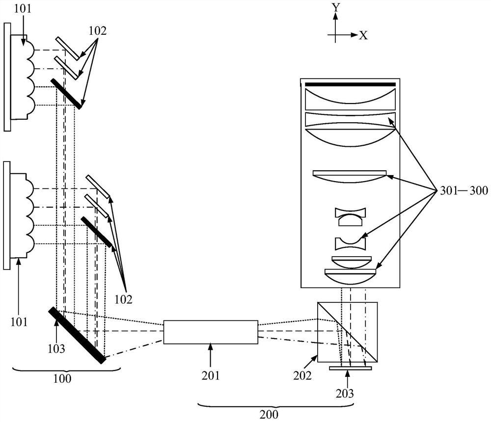
[0024] Please refer to figure 1 , figure 1 It is a schematic structural diagram of a laser projection device provided by an embodiment of the present application. The laser projection apparatus may include: a light source system 100 , an optical illumination system 200 and a projection lens 300 .

[0025] The light source system 100 in the laser projection device may include: a laser 101 , a light combining mirror group 102 and a first reflecting mirror 103 . The light-combining mirror group 102 may be located on the light-emitting side of the laser 101 , and the arrangement direction of the light-combining mirror group 102 and the laser 101 may be perpendicular to the arrangement direction of the light-combining mirror group 102 and th...


PUM


Abstract

The invention discloses laser projection equipment, and belongs to the field of projection display. The laser projection equipment comprises a light source system, an optical illumination system and a projection lens. The optical illumination system only adopts a single LCOS (Liquid Crystal On Silicon) to modulate the laser beam, so that the number of other optical devices matched with the single LCOS is small. In addition, the arrangement direction of the light combining mirror group and the first reflecting mirror in the light source system is parallel to the arrangement direction of the plurality of optical lenses in the projection lens, and the arrangement direction of the light uniformizing assembly and the light splitting assembly in the optical illumination system is perpendicular to the arrangement direction of the plurality of optical lenses. Therefore, the arrangement of the light source system, the optical illumination system and the projection lens is compact, so that the width of the laser projection equipment in the first direction is small, and the width of the laser projection equipment in the second direction is also small. In this way, the size of the whole laser projection equipment can be small.

Description

technical field [0001] The present application relates to the field of projection display, in particular to a laser projection device. Background technique [0002] With the development of optoelectronic technology, the requirements for the projection screen of laser projection equipment are getting higher and higher. At present, in order to ensure the display brightness of the projection screen, a laser is usually used to provide illumination for the laser projection equipment. The laser beam emitted by the laser has the advantages of good monochromaticity and high brightness, and is an ideal light source. [0003] At present, laser projection equipment usually includes: a laser light source, an illumination system and a projection lens. The lighting system usually includes: a uniform light component, a relay lens group, a dichroic mirror group, a reflector group, and three liquid crystal on Silicon (English: Liquid Crystal on Silicon; abbreviation: LCOS) (for example, red...

Claims


Application Information

Patent Timeline
IPC IPC(8): G03B21/20G03B21/00G02B27/10H04N9/31
CPCG03B21/2033G03B21/206G03B21/2066G03B21/208G03B21/006G02B27/1006H04N9/3152H04N9/3161H04N9/315H04N9/3102
Inventor 李晓平李巍
Owner QINGDAO HISENSE LASER DISPLAY CO LTD
Why Eureka
Try Eureka