
Self-cooled axial flux motor

An axial magnetic flux, self-cooling technology, used in cooling/ventilation devices, electromechanical devices, electrical components, etc., can solve the problems of magnetic performance decline of magnetic steel, demagnetization of magnetic steel, deformation of parts, etc., to improve the heat dissipation effect, The effect of reducing parts and increasing strength

Pending Publication Date: 2022-07-29
铜陵硬核派科技有限公司
View PDF0 Cites 1 Cited by
  • Summary
  • Abstract
  • Description
  • Claims
  • Application Information

AI Technical Summary

Problems solved by technology

In addition, the magnetic steel of the rotor will produce eddy current loss, and the magnetic plate will also produce iron loss. These losses will be converted into heat and accumulate in the rotor, resulting in excessive local heat of the rotor.
If the temperature of the rotor is too high, the magnetic performance of the magnetic steel will be greatly reduced, and in severe cases, the magnetic steel will be demagnetized
In addition, too high temperature will also cause deformation of parts on the rotor and unreliable fixation.
If the heat is not transferred to the outside of the motor in time, when the heat of the motor reaches a certain level, insulation breakdown will easily occur, causing the motor to burn out

Method used


Image

  • Self-cooled axial flux motor
  • Self-cooled axial flux motor
  • Self-cooled axial flux motor

Examples


Embodiment 2

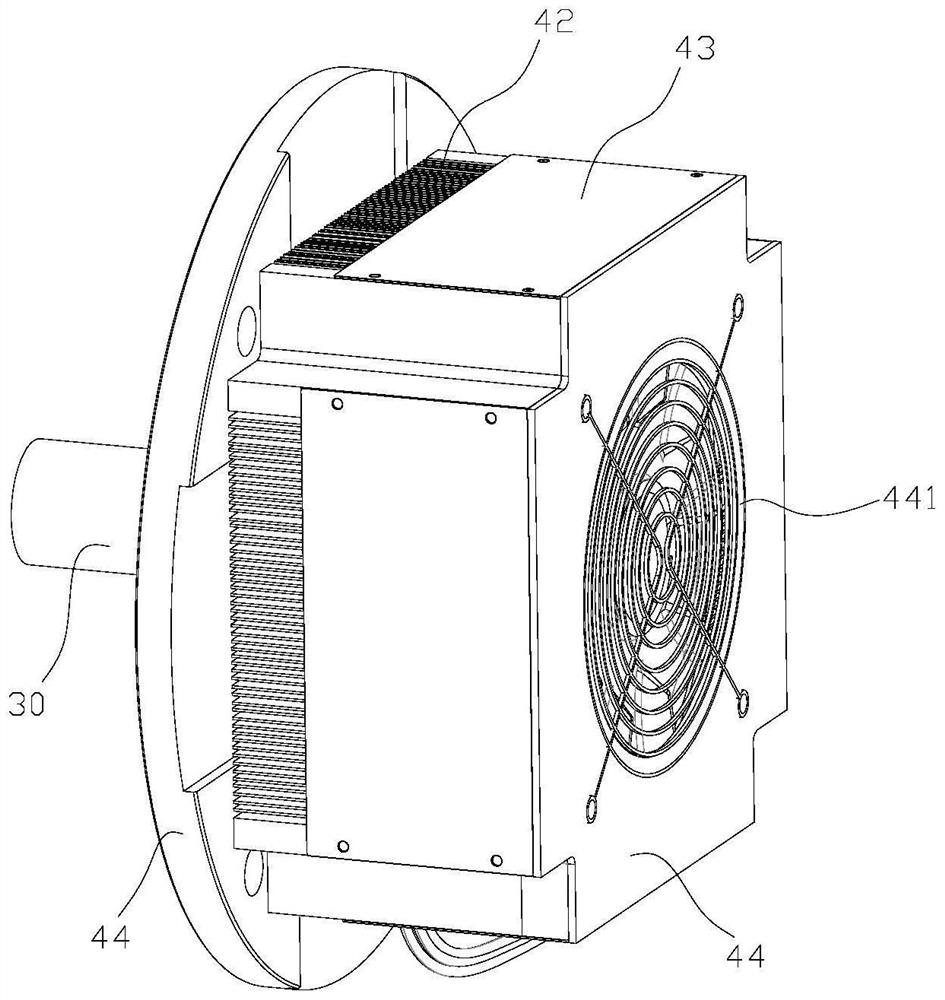
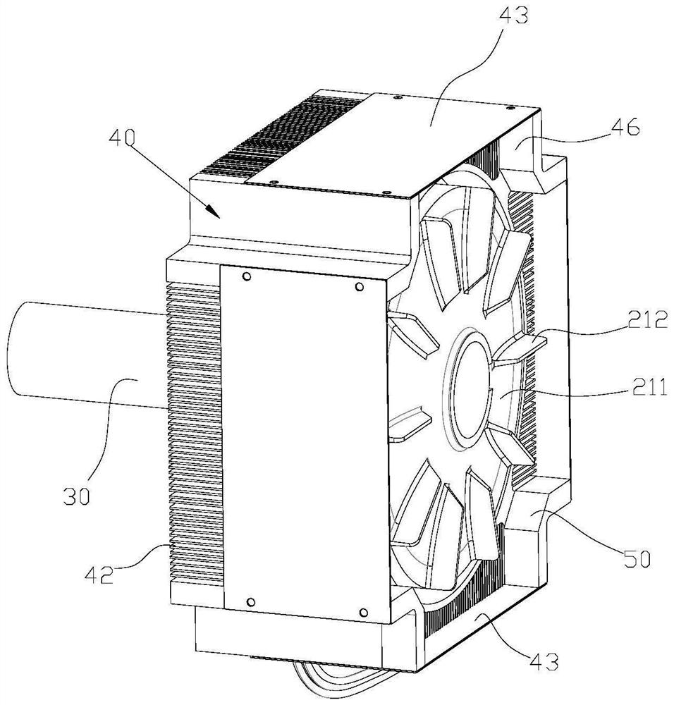
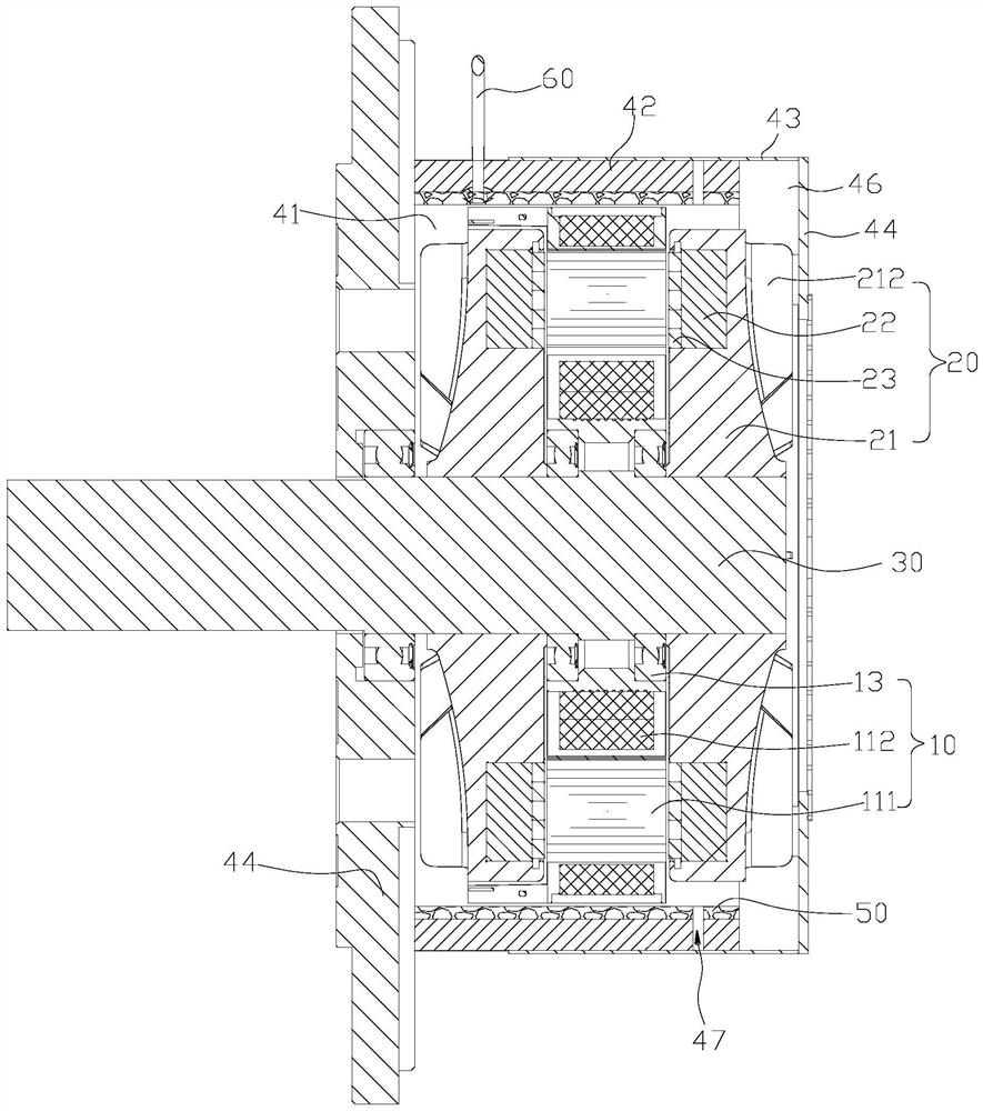
[0035] In order to make the reliability of the rotor more stable, a pressing rod 70 can be arranged at the gap between two adjacent pieces of magnetic steel 23, such as Figure 9-11 , at least one end of the pressing rod 70 is fixed on the rotor back plate 21 , and the shaft of the pressing rod 70 is pressed against the magnetic conducting plate 22 .

[0036] Further explanation is that the pressing rod 70 can be fixed on the rotor back plate 21 at one end, or can be fixed on the rotor back plate 21 at both ends. However, it must be ensured that the shaft of the pressing rod 70 is pressed on the magnetic conducting plate 22 . The specific structure used can be determined according to the diameter of the rotor. Generally, the large diameter rotor is fixed at both ends, while the pressure rod of the small diameter rotor is fixed by one end, and the other end can be overhanging and pressing to meet the fixing requirements. When installing, first put the magnetic conductive plate...


PUM


Abstract

The invention relates to the field of motors, in particular to a self-cooling axial magnetic flux motor which comprises a stator, a rotor, a rotating shaft and a machine shell, the machine shell is provided with a cavity used for containing the stator and the rotor, the rotating shaft sequentially penetrates through the stator and the rotor and then extends towards the two ends, the rotor comprises a rotor back plate, a magnetic conductive plate and magnetic steel, the rotor back plate is an open shell, and the magnetic steel is arranged in the cavity. The magnetic conductive plate is integrally in a circular ring shape, the magnetic conductive plate is arranged in a cavity of the rotor back plate, the magnetic steels are attached to the surface of one side, close to an opening of the rotor back plate, of the magnetic conductive plate, and the magnetic steels are uniformly arranged at intervals in the circumferential direction of the magnetic conductive plate. More than two fan blades are arranged on the outer side face of the bottom of the rotor back plate, the multiple fan blades are radially distributed with the geometric center of the rotor back plate as the center, the bottom space of the rotor back plate of the disc type motor is reasonably utilized, the fan and the rotor back plate are integrated, additional fans are avoided, the number of parts is reduced, and meanwhile the space is saved.

Description

technical field [0001] The invention relates to the field of motors, in particular to a self-cooling axial flux motor. Background technique [0002] The disc motor is an axial permanent magnet motor. The rotor of this motor is mainly composed of a rotor back plate, a magnetic conductive plate and a magnetic steel, wherein the magnetic steel and the magnetic conductive plate are fixed on the rotor back plate. The rotor maintains a high-speed operation for a long time during operation, and friction will occur between the rotor and the bearing, rotating shaft, oil seal, etc., and these mechanical frictions will generate a very large amount of heat. In addition, the magnetic steel of the rotor will generate eddy current loss, and the magnetic conductive plate will also generate iron loss. These losses will be converted into heat and accumulated in the rotor, causing the local heat of the rotor to be too high. If the temperature of the rotor is too high, the magnetic properties ...

Claims


Application Information

Patent Timeline
Patent Type & Authority Applications(China)
IPC IPC(8): H02K9/06H02K1/22H02K1/30H02K5/18H02K5/20
CPCH02K9/06H02K1/22H02K1/30H02K5/18H02K5/207
Inventor 陈拯民
Owner 铜陵硬核派科技有限公司
Learn More