Railway signal power supply system

A technology for power supply systems and railway signals, applied in control/regulating systems, electrical components, regulating electrical variables, etc., can solve the problems of large size and weight, load equipment power-off restart, and high configuration costs, to achieve parallel expansion, avoid Circulation problems, effects with a wide range of applications

Pending Publication Date: 2022-07-29
BEIJING DINGHAN TECH GRP CO LTD
View PDF0 Cites 0 Cited by
  • Summary
  • Abstract
  • Description
  • Claims
  • Application Information

AI Technical Summary

Problems solved by technology

[0004] However, these two methods have certain disadvantages: the first method is not easy to achieve expansion
In the case of large-capacity load applications, it is generally realized by the method of load splitting, but in order to realize redundant power supply, each bundle needs to be equipped with two 25Hz power supplies, and the configuration cost is high; The physical switching delay of the relay will generally cause a 30-60ms output interruption during the switching process. For non-delayed load equipment, it may cause the load equipment to be powered off and restarted; in addition, two 25Hz low-frequency transformers are required to realize input / output. Electrical isolation between output / output, relatively large volume and weight, and relatively high cost
Although the second method can achieve capacity expansion, there are still deficiencies, which are mainly reflected in two aspects: First, because the interior is not isolated, parallel machine expansion must input the same source, otherwise it may cause input side circulation, resulting in intermediate bus support The capacitor voltage is too high (normal bus capacitor voltage + line voltage rectification value), and even cause power supply damage, so the configuration flexibility is insufficient
Secondly, two 25Hz low-frequency transformers are still needed to realize the input / output, and the electrical isolation between the output / output, the volume and weight are relatively large, and the cost is relatively high

Method used


Image

  • Railway signal power supply system
  • Railway signal power supply system
  • Railway signal power supply system

Examples


Embodiment Construction

[0026] The present invention will be further described in detail below in conjunction with the accompanying drawings and embodiments. It should be understood that the specific embodiments described herein are only used to explain the present invention, but not to limit the present invention. In addition, it should be noted that, for the convenience of description, the drawings only show some but not all structures related to the present invention.

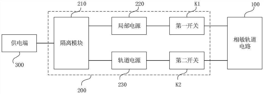
[0027] figure 1 It is a circuit structure block diagram of a railway signal power supply system provided in an embodiment of the present invention. refer to figure 1 , the railway signal power supply system includes: a phase-sensitive track circuit 100, a power supply terminal 300 and at least two power supply circuits 200; wherein, the power supply circuit 200 at least includes an isolation module 210, a local power supply 220, a track power supply 230, a first switch K1 and a second power supply circuit 200. Two switches K2, t...


PUM


Abstract

The embodiment of the invention discloses a railway signal power supply system. The railway signal power supply system comprises a phase-sensitive track circuit, a power supply end and at least two power supply circuits, the power supply circuit at least comprises an isolation module, a local power supply, a track power supply, a first switch and a second switch, the isolation module is electrically connected with the power supply end, the local power supply and the track power supply, the local power supply is electrically connected with the phase-sensitive track circuit through the first switch, and the track power supply is electrically connected with the phase-sensitive track circuit through the second switch; the isolation module is used for isolating a first input power supply signal input by a power supply end, outputting a first output power supply signal and a second output power supply signal, and respectively outputting the first output power supply signal and the second output power supply signal to a local power supply and a track power supply; the local power supply is used for outputting a first output power supply signal to the phase-sensitive track circuit according to the switching state of the first switch; the track power supply is used for outputting the second output power supply signal to the phase-sensitive track circuit according to the switching state of the second switch. Therefore, two paths of power supply can be provided for the phase-sensitive track circuit.

Description

technical field [0001] Embodiments of the present invention relate to the technical field of railways, and in particular, to a railway signal power supply system. Background technique [0002] In the field of railway signal power supply, 25Hz power supply is mainly used in electrified railways to supply power to railway 25Hz phase-sensitive track circuits. Among them, the track circuit uses the two rails of the railway as conductors, the two ends are insulated, and the closed circuit of the power transmission and power receiving equipment is connected, which is mainly used to monitor the occupancy of the line. The 25Hz power supply includes two outputs, one output is track output power (220V / 25Hz), and the other output is local output power (110V / 25Hz). The local output power phase is 90 degrees ahead of the track output power. [0003] There are only two existing 25Hz power supply modes: one is that the output adopts the main and standby output, that is, the two 25Hz powe...

Claims


Application Information

Patent Timeline
IPC IPC(8): H02M7/04H02M3/24H02M1/32H02M1/42
CPCH02M7/04H02M3/24H02M1/32H02M1/4208
Inventor 高国振
Owner BEIJING DINGHAN TECH GRP CO LTD
Why Eureka
Try Eureka