Single-dip-pipe vacuum refining device and using method thereof

A technology of vacuum refining and single dipping tube, which is applied in the field of molten steel refining outside the furnace, which can solve the problems of interruption of refining process, blockage of bottom blowing, deviation, etc., and achieve the effect of reducing oxidation, reducing erosion and improving service life

Active Publication Date: 2015-04-01
MAGANG (GROUP) HOLDING CO LTD +1
View PDF5 Cites 0 Cited by
  • Summary
  • Abstract
  • Description
  • Claims
  • Application Information

AI Technical Summary

Problems solved by technology

[0006] In order to overcome the problems existing in the prior art, the object of the present invention is to provide a vacuum refining device with a single dip tube, which changes the molten steel circulation mode of the existing vacuum refining device, and overcomes the blockage of the ladle bottom blowing brick or the disorder of the steel flow. The problem of interruption of the refining process caused by the bottom blowing gas deviating from the single dip tube also reduces the problem of corrosion of the vacuum chamber refractory material and reduces the cost of refining

Method used


Image

  • Single-dip-pipe vacuum refining device and using method thereof
  • Single-dip-pipe vacuum refining device and using method thereof

Examples


Embodiment 1

[0023]The single dipping tube vacuum refining device performs refining according to the following steps:

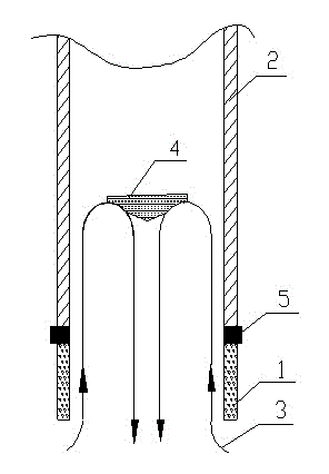
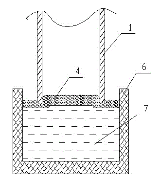
[0024] (1) When refining molten steel, first lift the ladle to the ladle car, and the ladle car drives into the treatment station of the single-dipping tube vacuum refining device, then insert the dipping tube into the ladle slag, vacuum the slag, and suck as much ladle slag as possible .

[0025] (2) Insert the dipping pipe into the molten steel to a depth of 400mm, open the nozzle valve on the circulation pipe of the dipping pipe, the blowing volume of each nozzle is equal, and the total blowing flow rate is controlled at 13NL / min per ton of steel.

[0026] (3) Vacuumize to reduce the vacuum degree to 73Pa after 3 minutes. Observe the top slag situation of the liquid steel surface in the vacuum chamber through the camera image of the vacuum chamber, and further adjust the total blowing flow rate of the nozzle to 18NL / min per ton of steel.

[0027] (4) After 10 min...

Embodiment 2

[0030] The single dipping tube vacuum refining device performs refining according to the following steps:

[0031] (1) When refining molten steel, first lift the ladle to the ladle car, and the ladle car drives into the treatment station of the single-dipping tube vacuum refining device, then insert the dipping tube into the ladle slag, vacuum the slag, and suck as much ladle slag as possible .

[0032] (2) Insert the dipping pipe into the molten steel to a depth of 400mm, open the nozzle valve on the circulation pipe of the dipping pipe, the blowing volume of each nozzle is equal, and the total blowing flow rate is controlled at 15NL / min per ton of steel.

[0033] (3) Vacuumize to reduce the vacuum degree to 70Pa after 3 minutes. Observe the top slag situation of the liquid steel surface in the vacuum chamber through the camera image of the vacuum chamber, and further adjust the total blowing flow rate of the nozzle to 20NL / min per ton of steel.

[0034] (4) After 11 mi...


PUM


Abstract

The invention discloses a vacuum refining device with a single dipping tube, which comprises a vacuum chamber and a dipping tube. During vacuum refining, the dipping tube is inserted into molten steel in a ladle. The nozzles of the same layer are grouped and controlled independently, and argon is blown into the dipping tube through the blowing nozzles on the inner wall of the single dipping tube. In the vacuum refining process, by increasing the blowing volume of the nozzle on the dipping tube, the molten steel forms a circulation that rises around the vacuum chamber and descends along the center of the vacuum chamber to achieve deep decarburization and deep desulfurization under vacuum. This device changes the molten steel circulation mode of the existing vacuum refining device, overcomes the blockage of the bottom blowing brick of the ladle or the interruption of the refining process caused by the bottom blowing gas deviating from the dipping tube due to steel flow disorder, and also reduces the corrosion of the refractory material in the vacuum chamber , also reduces the refining cost.

Description

technical field [0001] The invention belongs to the field of molten steel refining outside the furnace, in particular to a vacuum refining device for simultaneously producing ultra-low carbon and ultra-low sulfur steel. Background technique [0002] At present, the out-of-furnace refining method for industrial-scale production of ultra-low carbon and ultra-low sulfur steel mainly adopts RH vacuum refining. The main problems in the process of using RH vacuum refining to produce ultra-low carbon and ultra-low sulfur steel at the same time are as follows: First, the RH furnace is composed of two dipping tubes, rising and falling. The time is long, the dipping tube has serious nodules, and the life of the dipping tube is short. The second is that the RH furnace is composed of two dipping tubes that rise and fall. The inner diameter of the dipping tube is small and the steel slag interface is small. reach below 30%. In addition, because the desulfurizer used in it contains up t...

Claims


Application Information

Patent Timeline
Patent Type & Authority Patents(China)
IPC IPC(8): C21C7/10C21C7/068
CPCC21C7/068C21C7/064C21C7/10
Inventor 乌力平沈昶胡玉畅潘远望谢世红
Owner MAGANG (GROUP) HOLDING CO LTD
Why Eureka
Try Eureka