Unipolar modulation reactive zero crossing point current distortion control device and control method

A unipolar modulation, current distortion technology, applied in the output power conversion device, AC power input into DC power output, electrical components and other directions, can solve problems such as current distortion, to improve current distortion, increase control difficulty, The effect of not occupying computing resources

Pending Publication Date: 2022-07-29
SHENZHEN YINGFEIYUAN TECH CO LTD
View PDF0 Cites 0 Cited by
  • Summary
  • Abstract
  • Description
  • Claims
  • Application Information

AI Technical Summary

Problems solved by technology

[0005] The technical problem to be solved by the present invention is to provide a unipolar modulation reactive power zero-crossing point current distortion control device and control method, aiming to solve the problem of current distortion at the voltage zero-crossing point when grid-connected inverter outputs reactive power

Method used


Image

  • Unipolar modulation reactive zero crossing point current distortion control device and control method
  • Unipolar modulation reactive zero crossing point current distortion control device and control method
  • Unipolar modulation reactive zero crossing point current distortion control device and control method

Examples


Embodiment 1

[0049] like Figure 12 A schematic diagram of the frame structure of the control device provided in this embodiment is shown. In order to solve the above-mentioned problem of current distortion when transmitting reactive power, the present invention provides a unipolar modulation reactive power zero-crossing point current distortion control in the first embodiment. The device includes: a totem pole topology, a control module and a drive module.

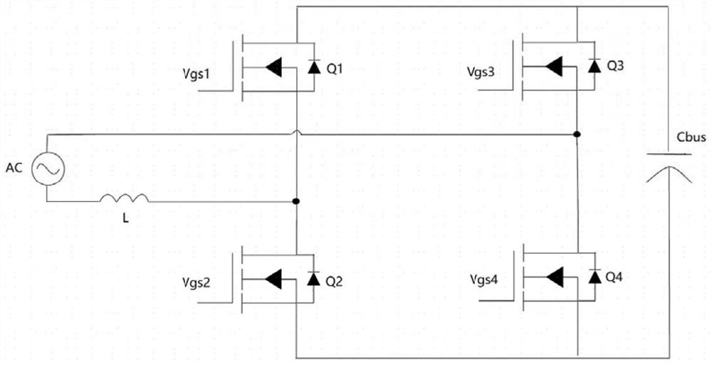
[0050] In this embodiment, the totem pole topology shown is a standard totem pole topology infrastructure, such as figure 1 The schematic diagram of the totem pole topology shown, including AC input / output end, PFC inductor, high frequency tube, power frequency tube and flow input / output end; wherein, the high frequency tube includes a high frequency upper tube and a high frequency lower tube. The frequency tube includes a power frequency upper tube and a power frequency lower tube, and the high frequency upper tube, the high frequen...

Embodiment 2

[0065] The second embodiment of the present invention provides a unipolar modulation reactive zero-crossing point current distortion control method, which is applied to the first embodiment to provide a unipolar modulation reactive zero-crossing current distortion control device, which will not be repeated here.

[0066] like Figure 14 As shown, the control method includes:

[0067] Step 140, the control module receives the sampling signal of the totem pole topology, and based on the sampling signal, outputs the first high frequency PWM signal and the second high frequency PWM signal of the same frequency.

[0068] Wherein step 141 specifically includes:

[0069] The loop computing unit receives the sampling signal of the totem pole topology, and outputs a sine-like wave according to the sampling signal. The modulation wave is calculated by outputting a sine-like wave similar to the grid voltage through the control loop. Figure 15 As shown, the loop calculates and outputs...


PUM


Abstract

The invention provides a unipolar modulation reactive zero crossing current distortion control device and method, the control device comprises a totem pole topology, a control module and a driving module, and the control method comprises the following steps: the control module receives a sampling signal of the totem pole topology, and calculates a current distortion value of the totem pole topology based on the sampling signal; a first high-frequency PWM signal and a second high-frequency PWM signal with the same frequency are output; the driving module outputs a power frequency tube driving signal according to the first high-frequency PWM signal and outputs a high-frequency tube driving signal according to the second high-frequency PWM signal; a high-frequency tube in the totem-pole topology is driven according to the high-frequency tube driving signal, and a power frequency tube is driven according to the power frequency tube driving signal. According to the invention, the high-frequency PWM signal with the same frequency is output based on the same sampling signal, synchronous commutation of the power frequency tube and the high-frequency tube is completed, and current distortion at a zero crossing point, especially current distortion when grid-connected inverter outputs reactive power, is improved.

Description

technical field [0001] The invention belongs to the field of circuit electronics, in particular to a unipolar modulation reactive zero-crossing point current distortion control device and a control method. Background technique [0002] The commonly used structure of totem pole topology is a pair of high frequency switch tubes (referred to as high frequency tubes) and a pair of power frequency switch tubes (referred to as power frequency tubes). The basic topology is as follows: figure 1 As shown, Q1 and Q2 are high-frequency tubes, Q3 and Q4 are power-frequency tubes, and their basic working principle is: the grid voltage polarity is as follows figure 1 As shown, the power frequency tube Q3 is turned on, and the circuit has two main working modes, mode 1 ( figure 2 ) and modal 2 ( image 3 ), unipolar modulation is performed by the high-frequency switches of Q1 and Q2; when the grid voltage is reversed, Q4 is turned on, and other principles are the same. In the case of i...

Claims


Application Information

Patent Timeline
Patent Type & Authority Applications(China)
IPC IPC(8): H02M7/797H02M7/81H02M1/08H02M1/088
CPCH02M7/797H02M7/81H02M1/083H02M1/088H02M1/0038H02M1/0012
Inventor 赵文泽雷彪
Owner SHENZHEN YINGFEIYUAN TECH CO LTD
Why Eureka
Try Eureka