
Combined wave-front corrector based on conjugate imaging

A wavefront corrector and combined technology, applied in the directions of instruments, optical components, optics, etc., can solve the problems of inconvenience in the manufacture of a single wavefront corrector and a large number of driving units, and increase the number of driving units and driving units. Reduce and overcome the effect of excessive toughness requirements

Inactive Publication Date: 2009-12-23
INST OF OPTICS & ELECTRONICS - CHINESE ACAD OF SCI
View PDF3 Cites 0 Cited by
  • Summary
  • Abstract
  • Description
  • Claims
  • Application Information

AI Technical Summary

Problems solved by technology

Each deformable mirror in MCAO is not on the conjugate plane of the object image, and the number of such driving units is relatively large, which is not convenient for the manufacture of a single wavefront corrector

Method used


Image

  • Combined wave-front corrector based on conjugate imaging
  • Combined wave-front corrector based on conjugate imaging
  • Combined wave-front corrector based on conjugate imaging

Examples


Embodiment Construction

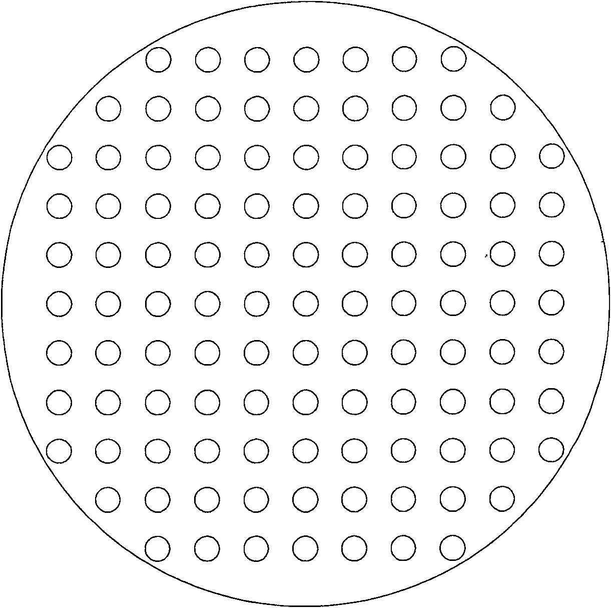
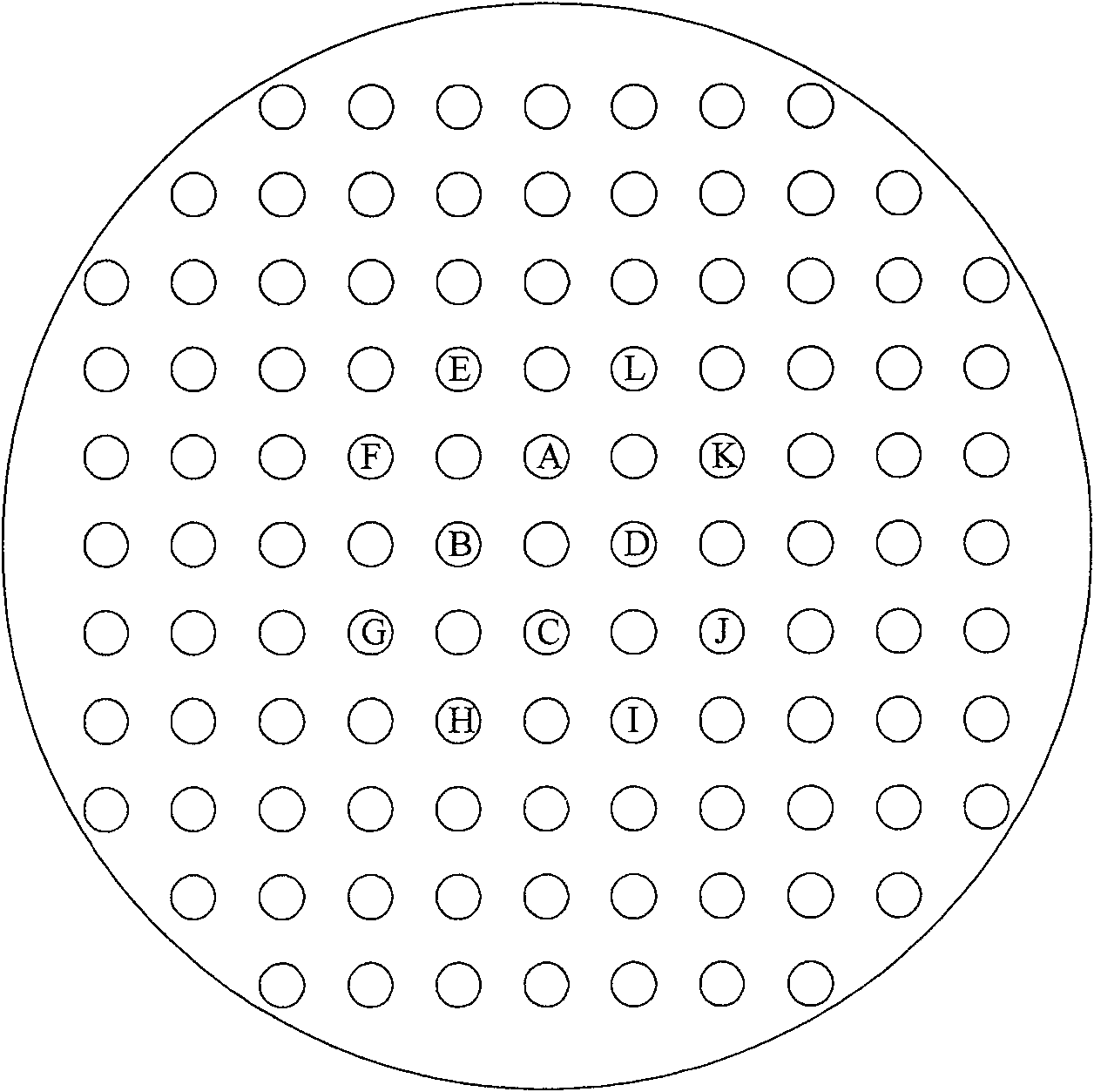
[0028] Such as figure 1 As shown, in a large-aperture ground-based telescope adaptive optics system, if the aperture of the primary mirror of the telescope is D, and the atmospheric coherence length is r0, according to (D / r0) 2 , to get the number of driving units of the wavefront corrector to be manufactured, and arrange them in a square, the small circle in the figure is a driving unit. We use the symmetry operation in the plane point group to split these drive units into several categories, and each category corresponds to a wavefront corrector, so as to achieve the purpose of reducing the number of drive units on each wavefront corrector. The specific classification or corresponding to several wavefront correctors is determined by the manufacturing level of the wavefront correctors.

[0029] A specific splitting step is as follows figure 2 As shown, the explanation is as follows:

[0030] 1. Assuming that the drive unit spacing is d0, find four equally spaced drive un...


PUM


Abstract

A combined wavefront corrector based on the conjugate imaging, including: some wavefront correctors and 4f optics system, the quantity of the wavefront corrector can be two, three or more, the wavefront corrector can use the piezoelectric ceramics (PZT) or electrostrictive ceramics (PMN) as the driver to produce the specular anamorphotic mirror, can be the bimorph mirror, can use micro-electromechanical system (MEMS) technology to produce the anamorphotic mirror, can be the liquid crystal space light modulator parts (LC- SLM); the 4f optics system can use lens structure and also use off-axis reflective parabolic reflector structure, the 4f optics system connects the nearby wavefront correctors in turn to form a combined wavefront corrector, and every wavefront corrector is at the optics conjugate imaging location.

Description

technical field [0001] The invention relates to a wavefront corrector for an adaptive optics system of a ground-based telescope, in particular to a combined wavefront corrector based on conjugate imaging. Background technique [0002] Most of the current wavefront correctors used for wavefront correction in adaptive optics systems of ground-based telescopes are based on a single deformable mirror. With the increase of the aperture (diameter D) of the primary mirror of the telescope, in order to achieve a better wavefront correction effect, the number of drive units (N) of the deformable mirror increases rapidly. Assuming that the coherence length of the atmospheric disturbance is r0, then N is proportional to (D / r0) 2 . In the visible light adaptive optics system, when the aperture of the primary mirror is on the order of four meters, the number of drive units of the deformable mirror needs to be thousands of units. reached tens of thousands. It is very difficult and exp...

Claims


Application Information

Patent Timeline
Patent Type & Authority Patents(China)
IPC IPC(8): G02B27/00
Inventor 张雨东刘桂林
Owner INST OF OPTICS & ELECTRONICS - CHINESE ACAD OF SCI
Learn More