Liftable axle mechanism of new energy truck
A new energy and truck technology, applied in vehicle components, electric vehicles, vehicle energy storage, etc., can solve problems such as safety hazards, wheel suspension, truck tilting, etc., and achieve the effect of avoiding safety hazards
- Summary
- Abstract
- Description
- Claims
- Application Information
AI Technical Summary
Problems solved by technology
Method used
Image

Examples
Embodiment 1
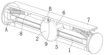
[0027] see figure 1 , image 3 and Image 6 , The present invention provides a liftable axle mechanism for new energy trucks that avoids large-angle inclination or suspended wheels when the trucks are parked and met, including an axle body 1, and a rotating cylinder 2 is arranged in the middle of the axle body 1, and the axle The two ends of the body 1 are rotatably connected with two mounting blocks 3. The mounting block 3 is provided with a mounting plate 4 on the outside. The rotating cylinder 2 is provided with a rotating mechanism 5 inside. 7 is arranged above the rotating cylinder 2, and both ends are provided with a lifting mechanism 8, and one side of the support plate 7 is provided with a regulating component 9.
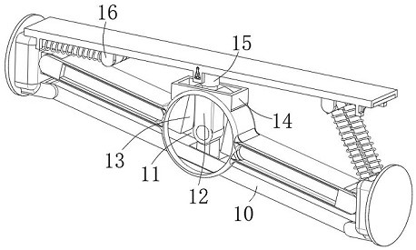
[0028] see figure 1 In the figure, the rotating mechanism 5 includes a rotating rod 10, the two ends of the rotating rod 10 are respectively connected with one end of the two mounting blocks 3 in rotation, the rotating cylinder 2 is provided with a rotati...
Embodiment 2
[0033] see figure 1 , figure 2 , Figure 4 , Figure 5 , Image 6 and Figure 8, This embodiment further illustrates Embodiment 1. The present invention provides a liftable axle mechanism for new energy trucks that avoids large-angle inclination or suspended wheels when the trucks are parked and met, including a vehicle axle body 1, a vehicle axle body 1. There is a rotating cylinder 2 in the middle, two mounting blocks 3 are rotatably connected at both ends of the axle body 1, a mounting plate 4 is provided on the outer side of the mounting block 3, a rotating mechanism 5 is provided inside the rotating cylinder 2, and a rotating mechanism 5 is provided on the upper side of the rotating cylinder 2. The support mechanism 6, the support plate 7, the support plate 7 is arranged above the rotating cylinder 2, and the two ends are provided with a lifting mechanism 8, and one side of the support plate 7 is provided with a control assembly 9.
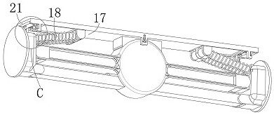
[0034] see figure 2 and Figu...
Embodiment 3
[0038] see figure 1 , image 3 , Image 6 and Figure 7 , this embodiment further illustrates Embodiment 2, the present invention provides a new energy truck liftable axle mechanism that avoids large-angle inclination or suspended wheels when the truck is parked and met, including a vehicle axle body 1, a vehicle axle body 1. There is a rotating cylinder 2 in the middle, two mounting blocks 3 are rotatably connected at both ends of the axle body 1, a mounting plate 4 is provided on the outer side of the mounting block 3, a rotating mechanism 5 is provided inside the rotating cylinder 2, and a rotating mechanism 5 is provided on the upper side of the rotating cylinder 2. The support mechanism 6, the support plate 7, the support plate 7 is arranged above the rotating cylinder 2, and the two ends are provided with a lifting mechanism 8, and one side of the support plate 7 is provided with a control assembly 9.
[0039] see image 3 and Image 6 , in the figure, the clamping ...
PUM
 Abstract
Description
Claims
Application Information
 - R&D
- Intellectual Property
- Life Sciences
- Materials
- Tech Scout
- Unparalleled Data Quality
- Higher Quality Content
- 60% Fewer Hallucinations
Browse by: Latest US Patents, China's latest patents, Technical Efficacy Thesaurus, Application Domain, Technology Topic, Popular Technical Reports.
© 2025 PatSnap. All rights reserved.Legal|Privacy policy|Modern Slavery Act Transparency Statement|Sitemap|About US| Contact US: help@patsnap.com