Signal transmission line collecting equipment

A technology of signal transmission line and collection equipment, applied in transportation and packaging, information technology support system, comprehensive factory control, etc., can solve the problems of occupying collection box space, unable to achieve collection effect, transmission line unable to be coiled, etc., to ensure The effect of collecting quality, improving collecting efficiency, and improving the degree of tightening

Active Publication Date: 2022-08-02
烟台海上航天科技有限公司 +1
View PDF7 Cites 0 Cited by
  • Summary
  • Abstract
  • Description
  • Claims
  • Application Information

AI Technical Summary

Problems solved by technology

[0003] The Chinese invention patent with the application number 201811556703.7 discloses a signal transmission line collection device, which hooks the protrusions at the left and right ends of the signal transmission line by setting a fixed hook, so as to drive the transmission line to move and collect, and also to automatically identify different The function of the signal transmission line, but the design of the fixed hook is obviously flawed. When the fixed hook moves to the far right, the protrusion of the transmission line will break away from the fixed hook. Good collection effect, and the collection of the transmission line can not control its tightness, the transmission line cannot be coiled for collection, occupying the space of the collection box

Method used


Image

  • Signal transmission line collecting equipment
  • Signal transmission line collecting equipment
  • Signal transmission line collecting equipment

Examples


Embodiment Construction

[0029] The technical solutions in the embodiments of the present invention will be clearly and completely described below with reference to the accompanying drawings in the embodiments of the present invention. Obviously, the described embodiments are only a part of the embodiments of the present invention, but not all of the embodiments. Based on the embodiments of the present invention, all other embodiments obtained by those of ordinary skill in the art without creative efforts shall fall within the protection scope of the present invention.

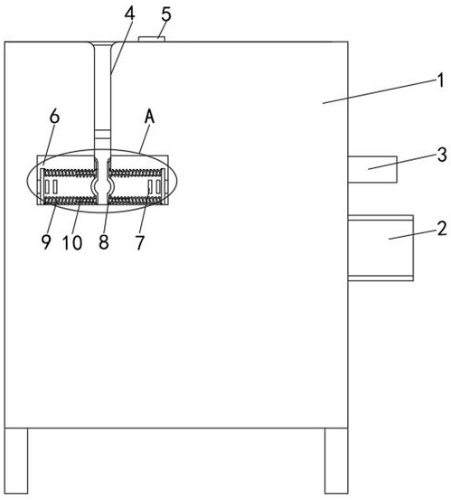
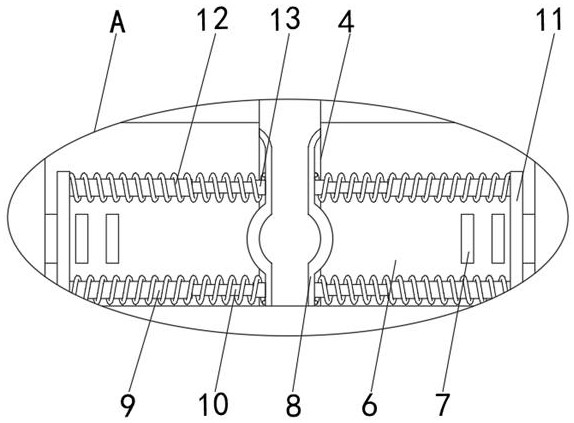
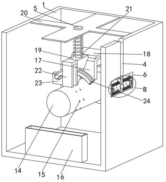
[0030] like Figure 1 to Figure 9 As shown, the embodiment of the present invention provides a signal transmission line collection device, including a collection box 1, a deceleration motor 2, a hydraulic rod 3 and a storage box 16. The front of the collection box 1 is provided with a wire pay-off slot 4. The bottom is provided with a placement slot 6, and the interior of the placement slot 6 is provided with two clamping arc plates 8...


PUM


Abstract

The invention belongs to the technical field of signal transmission line collection, and discloses signal transmission line collection equipment which comprises a collection box, a gear motor, a hydraulic rod and a storage box, a pay-off groove is formed in the front face of the collection box, a placement groove is formed in the bottom of the pay-off groove, and two clamping arc plates are arranged in the placement groove; the opposite faces of the two clamping arc plates are fixedly connected with rubber blocks and first springs, the ends, not connected with the rubber blocks, of the first springs are fixedly connected with limiting plates, and the two sides of the front face of the containing groove are fixedly connected with three clamping plates. A hydraulic rod drives an extrusion plate and a top plate leftwards, an adaptive block is synchronously driven to move upwards, then a limiting frame is made to move upwards, the adaptive block pushes wound and collected signal transmission lines into a storage box to complete collection while driving the limiting frame upwards, all-directional limiting and clamping in the collection process can be achieved, and the collection efficiency is improved. The collection quality is ensured, and the collection efficiency is improved.

Description

technical field [0001] The invention belongs to the technical field of signal transmission line collection, in particular to a signal transmission line collection device. Background technique [0002] The signal transmission line is used to transmit information and control information in the electrical control circuit. The outer surface is wrapped with an insulating layer and has high reliability. It includes coaxial signal lines, digital signal lines and optical fiber signal lines. The signal transmission line is used in Collection needs to be done after the end, therefore, a signal transmission line collection device is required. [0003] The Chinese invention patent with the application number of 201811556703.7 discloses a signal transmission line collection device, which is provided with fixed hooks to hook the left and right ends of the signal transmission line, so as to drive the transmission line to move and collect, and also to automatically identify different The f...

Claims


Application Information

Patent Timeline
IPC IPC(8): B65H54/44B65H65/00B65H67/04B65H59/10
CPCB65H54/44B65H65/00B65H67/0411B65H59/10B65H2701/34Y04S40/124
Inventor 岳峰张国红刘永建白龙雷徐重阳
Owner 烟台海上航天科技有限公司
Why Eureka
Try Eureka