Pneumatic automatic temperature adjusting thermostat and adjusting method thereof

A thermostat, automatic technology, applied in the direction of engine components, engine cooling, machine/engine, etc.

Active Publication Date: 2022-08-02
湖北汉瑞景汽车智能系统有限公司
View PDF4 Cites 0 Cited by
  • Summary
  • Abstract
  • Description
  • Claims
  • Application Information

AI Technical Summary

Problems solved by technology

[0005]The main purpose of the present invention is to provide a pneumatic automatic thermostat and its adjustment method, to solve the problem that traditional thermostats cannot implement precise size adjustment according to the engine working needs Problems with loop flow control

Method used


Image

  • Pneumatic automatic temperature adjusting thermostat and adjusting method thereof
  • Pneumatic automatic temperature adjusting thermostat and adjusting method thereof
  • Pneumatic automatic temperature adjusting thermostat and adjusting method thereof

Examples


Embodiment 1

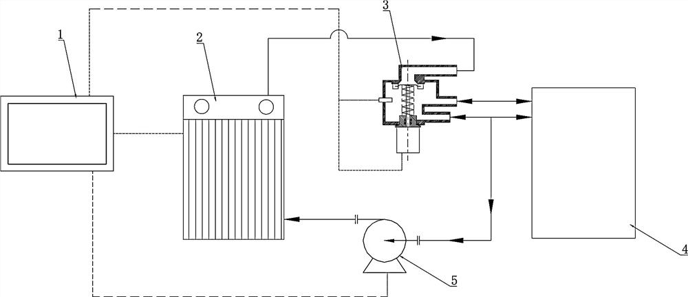
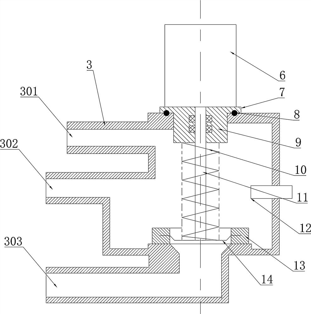
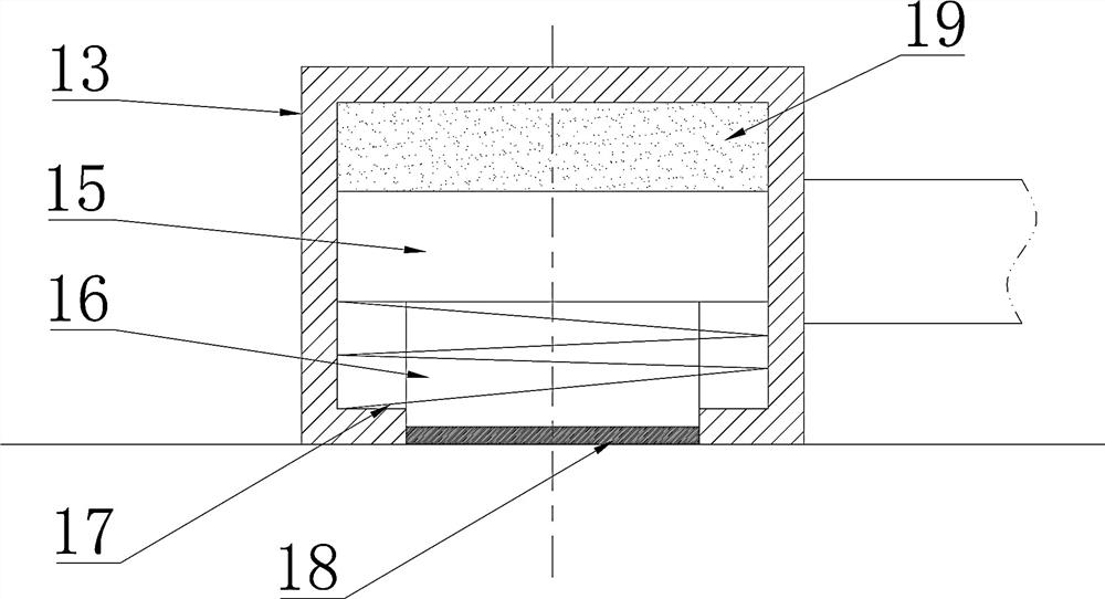
[0032] like Figures 1~5 As shown, a pneumatic automatic thermostat, the cavity of the thermostat 3 is provided with three connection ports, including a first connection port 301, a second connection port 302 and a third connection port 303, the thermostat 3 cavity There is a pneumatic element 6 on the body, the end of the piston rod 11 of the pneumatic element 6 is provided with a sealing pressing ring 13, the third connecting port 303 and the connecting port of the thermostat 3 cavity are arranged coaxially with the piston rod 11, and the sealing and pressing The ring 13 abuts against the third connection port 303 , so that the third connection port 303 is connected with the first connection port 301 and the second connection port 302 , and the temperature sensor 12 is also provided in the cavity of the thermostat 3 . When the engine 4 is just pneumatic, the water temperature decreases, the temperature sensor 12 is lower than the set value X, and the changed value is transmi...

Embodiment 2

[0043] Further illustrate in conjunction with embodiment 1, as Figure 1-5 In the structure shown, when the engine 4 is just pneumatic, the water temperature decreases, the temperature sensor 12 is lower than the set value X, and the changed value is transmitted to the controller 1, and the controller 1 controls the pneumatic element 6 to extend the piston rod 11, and the piston rod 11 The sealing plate 14 at the end is tightly pressed against the third connection port 303 of the large circulation, at this time, the first connection port 301 and the outlet of the second connection port 302 are connected, and the cooling water is in the small circulation.

[0044] After the engine 4 runs for a period of time, the water temperature is raised, the temperature sensor 12 should have a temperature higher than the set value X, and transmit the water temperature to the controller 1 in real time. The controller 1 controls the pneumatic element 6 to shrink the piston rod 11, and will Th...


PUM


Abstract

The invention provides a pneumatic automatic temperature adjusting thermostat and an adjusting method thereof.A thermostat cavity is provided with three connecting ports including the first connecting port, the second connecting port and the third connecting port, the thermostat cavity is provided with a pneumatic element, the end of a piston rod of the pneumatic element is provided with a sealing pressing ring, and the sealing pressing ring is connected with the first connecting port and the second connecting port. The third connecting port, the thermostat cavity connecting port and the piston rod are coaxially arranged, the sealing pressing ring abuts against the third connecting port, so that the third connecting port, the first connecting port and the second connecting port are connected and disconnected, and a temperature sensor is further arranged in a cavity of the thermostat. And pneumatic control is adopted and can be completed instantly. The delay efficiency of paraffin is eliminated, and the influence of engine overheating is reduced. And meanwhile, the situation that the working efficiency of the engine is reduced due to the fact that the paraffin wax is hysteretic and the warming time of the engine is too long due to short stop is avoided. In addition, the improvement of the efficiency of the engine has the most direct feeling to consumers that the oil consumption of the automobile is reduced, the power performance is stronger, and the reaction is quicker.

Description

technical field [0001] The invention relates to the field of thermostats, in particular to a pneumatic automatic thermostat and an adjustment method thereof. Background technique [0002] The existing thermostat controls the opening and closing of large and small circulation valves through the principle of thermal expansion and contraction of paraffin. The physical properties of paraffin are destined to have two shortcomings: response delay and hysteresis. In the process of engine warm-up, when the temperature reaches the melting point of paraffin, the expansion of paraffin causes the main valve of the thermostat to open, and the large cycle is opened. Because the physical process of thermal expansion and contraction of paraffin has a time delay, the temperature rises slowly. Causes the engine to warm up for too long; in the process of engine shutdown, paraffin needs to go through a long hysteresis process. [0003] When the temperature of the coolant reaches the specified...

Claims


Application Information

Patent Timeline
IPC IPC(8): F01P7/16
CPCF01P7/164
Inventor 时宇周学亮司学银廖艳军
Owner 湖北汉瑞景汽车智能系统有限公司
Why Eureka
Try Eureka