Industrial enzyme reaction monitoring system
A monitoring system and enzyme reaction technology, applied in the direction of enzyme production/bioreactor, bioreactor/fermenter combination, specific-purpose bioreactor/fermenter, etc. Problems such as low response ability, to achieve the effect of uniform reduction of water flow, improvement of momentum, and change of opening direction
- Summary
- Abstract
- Description
- Claims
- Application Information
AI Technical Summary
Problems solved by technology
Method used
Image

Examples
Embodiment 1
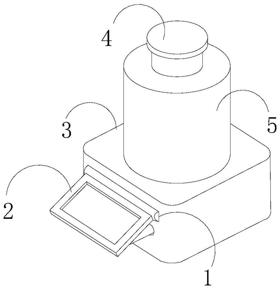
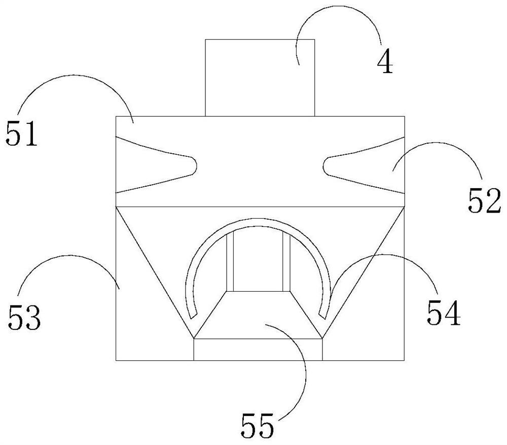
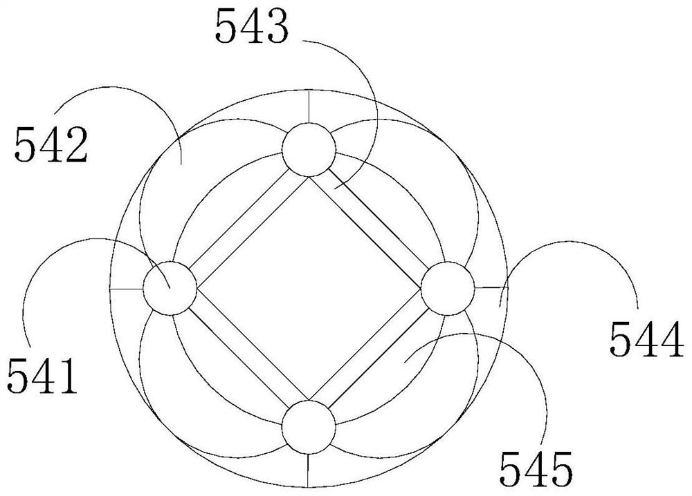
[0027] like Figure 1-Figure 3 As shown in the figure, the present invention provides an industrial enzyme reaction monitoring system. 3, the settling tank 3 is indirectly matched with the feeding cylinder 4 through the reaction cylinder 5, and the reaction cylinder 5 includes a looper 51, a distribution table 52, a concentration wall 53, and a booster 54. The looper The feeding cylinder 4 is fixedly connected to the 51, and is welded to the concentration wall 53, and the distribution table 52 is embedded and connected between the concentration walls 53. 54 includes a cross-over button 541, a slow-flow device 542, a licker-in 543, a wave extension plate 544, and a ring guide 545. The cross-over button 541 is fixedly connected to the wave extension plate 544, and rotates with a licker-in roll 543. The licker-in roll 543 Indirectly fit on the ring guide 545, the wave extension plate 544 is provided with a slow flow device 542, the wave extension plate 544 is an inverted hemisph...
Embodiment 2
[0029] like Figure 4-Figure 7 As shown, on the basis of Embodiment 1, the present invention combines the mutual cooperation of the following structural components. The ring guide 545 includes a top plate 451, a clip 452, a dredging ball 453, a support pad 454, and a four-shot table 455. The top plate 451 is provided with four, one end is inclined and fixedly connected to the four-shot table 455, and the other end is welded and connected with a support pad 454, and the support pad 454 is hingedly connected with a buckle clip 452 through the dredging ball 453, and the buckle clip 452 indirectly Fitted between the engagement button 541 and the licker-in roller 543, the slow flow device 542 includes a partition groove 421, an anti-support structure 422, a guide layer 423, a rolling ball 424, and a bite strip 425, and the partition groove 421 passes through the bite strip 425. It is hingedly connected to the support pad 454 and welded to the guide layer 423. Between the guide laye...
PUM
 Abstract
Description
Claims
Application Information