Joint robot of automatic material turning numerical control equipment

A numerical control equipment and automatic material turning technology, applied in the direction of comprehensive factory control, metal processing, etc., can solve the problems of reducing processing technology circulation and unevenness, and achieve the effect of reducing processing technology circulation and reducing stacking space

Pending Publication Date: 2022-08-05
SHENZHEN FSJ INTELLIGENT TECH CO LTD
View PDF13 Cites 0 Cited by
  • Summary
  • Abstract
  • Description
  • Claims
  • Application Information

AI Technical Summary

Problems solved by technology

[0005] Aiming at the problems existing in the prior art, the object of the present invention is to provide an automatic material-turning numerical control equipment joint robot. In this solution, a multi-processing surface automatic turning mechanism for turning over the workpiece body is added to the second fixed bracket, and the positioning surface automatically rotates. Mechanism, the multi-set gripper grabbing mechanism and the joint robot body used to grab the workpiece can complete the automatic loading and unloading of the workpiece body and the automatic flipping of multiple processing surfaces and automatic rotation of the positioning surface during the process conversion process, without manual flipping The workpiece body can greatly save manpower and labor. It can complete the finished product production of multi-process products with a single machine, reduce the circulation of processing technology, reduce the stacking space and retention problems of workpieces, and no longer have the trouble of uneven machine ratio. Let the machine All-weather operation is no longer difficult and expensive, fully excavating machine capacity, so that the processing industry no longer has the trouble of being restricted by personnel and difficult to manage, so that the processing industry no longer has the trouble of uncontrollable costs

Method used


Image

  • Joint robot of automatic material turning numerical control equipment
  • Joint robot of automatic material turning numerical control equipment
  • Joint robot of automatic material turning numerical control equipment

Examples


Embodiment

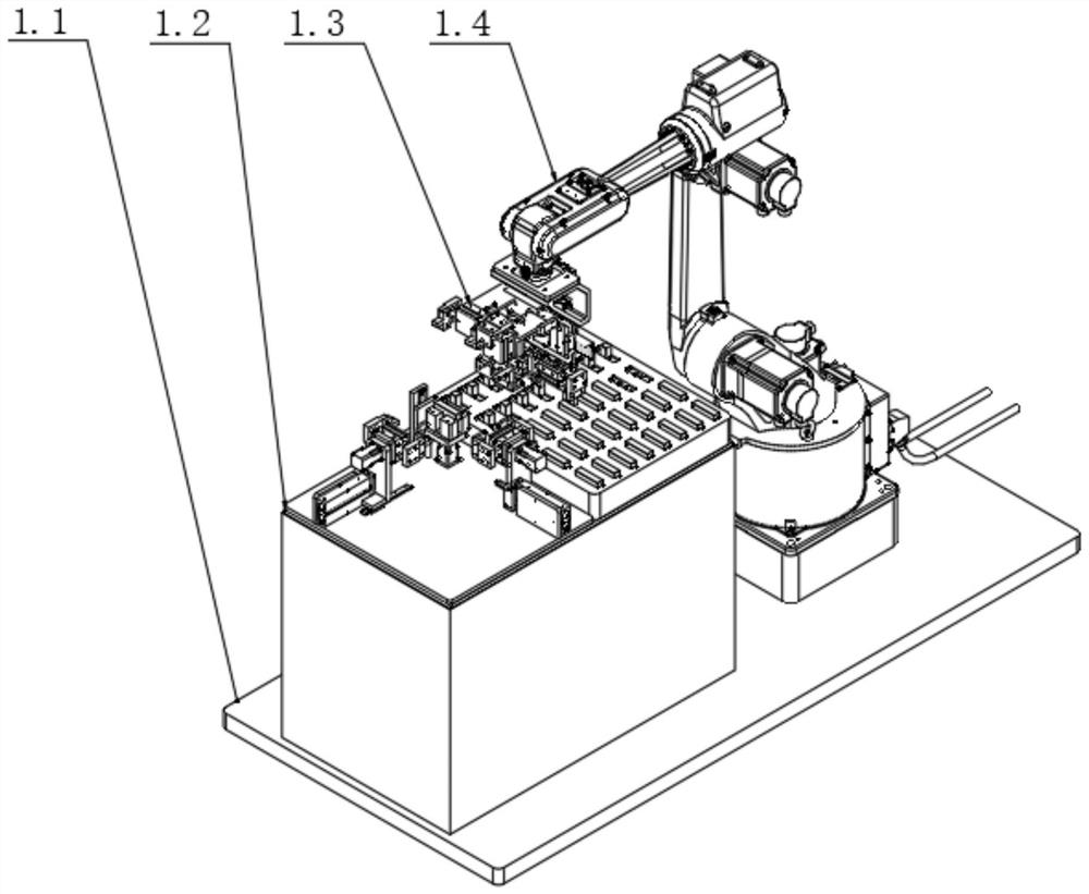
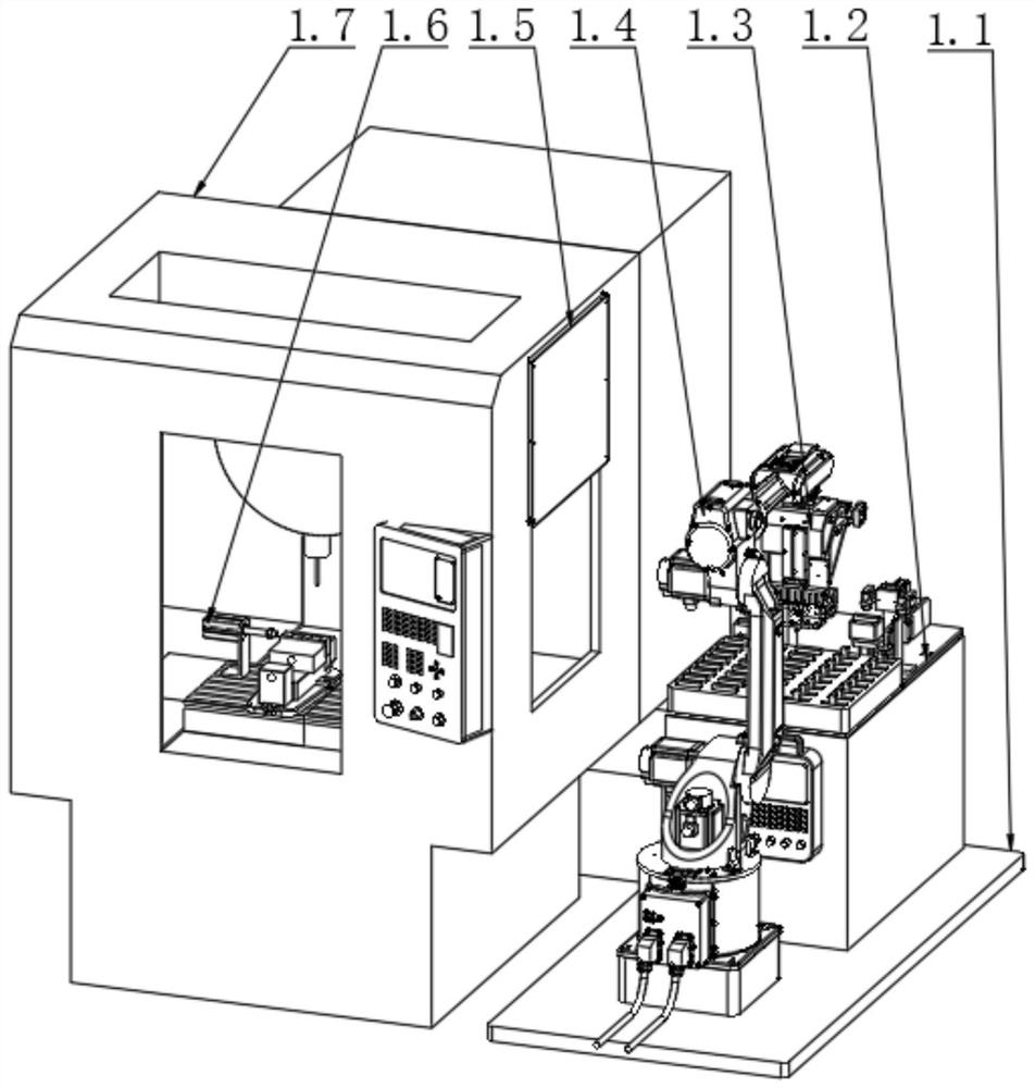
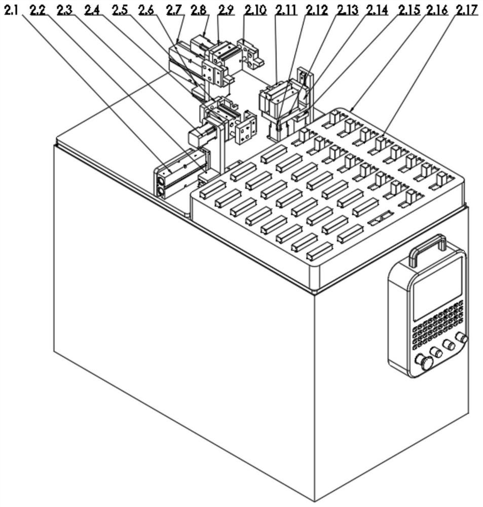
[0042] see Figure 1-2 , automatic turning over CNC equipment joint robot, including a first fixed bracket 1.1, the outer end of the first fixed bracket 1.1 is respectively equipped with a joint robot body 1.4 and a second fixed bracket 1.2, the upper end of the joint robot body 1.4 is equipped with a clamping jaw The grasping mechanism 1.3, the outer end of the joint robot body 1.4 is equipped with a numerical control device 1.7, the numerical control device 1.7 is provided with an auxiliary positioning mechanism 1.6, the outer end of the numerical control device 1.7 is equipped with a numerical control device telescopic door 1.5, on the second fixed bracket 1.2 The automatic turning mechanism of the processing surface, the rotating mechanism of the positioning surface and the material tray 1 2.16 are respectively installed, and the workpiece body 2.17 is arranged on the material tray 1 2.16. In this scheme, a multi-unit for turning the workpiece body 2.17 is added on the seco...


PUM


Abstract

The invention discloses an automatic turning numerical control equipment joint robot, which belongs to the field of machining, and is characterized in that a multi-machining surface automatic turning mechanism for turning a workpiece body, a positioning surface automatic rotating mechanism, a plurality of groups of clamping jaw grabbing mechanisms for grabbing workpieces and a joint robot body are additionally arranged on a second fixed bracket; automatic turning of multiple machining faces and automatic rotation of a positioning face in the process of automatic feeding and discharging of a workpiece body and procedure conversion can be completed, manual turning of the workpiece body is not needed, the labor-saving and labor-saving effects are greatly achieved, finished product manufacturing of multi-procedure products can be completed through a single machine, machining process circulation is reduced, the workpiece stacking space and the workpiece retention problem are reduced, and the production efficiency is improved. And the trouble of uneven matching of the machine is avoided, all-weather operation of the machine is no longer difficult and expensive, the capacity of the machine is fully excavated, the trouble of difficulty in management by personnel in the processing industry is no longer avoided, and the trouble of uncontrollable cost in the processing industry is no longer avoided.

Description

technical field [0001] The invention relates to the field of mechanical processing, and more particularly, to a joint robot of automatic material turning numerical control equipment. Background technique [0002] The traditional loading and unloading joint robot is composed of a joint robot, a gripper grasping mechanism on the robot, and a material preparation frame outside the CNC machining equipment. Taking the CNC machining center as an example: the working method is to grasp the gripper on the joint robot. The mechanism grabs the workpiece to be processed to the workpiece clamping point position at the vise (or other clamping mechanism) of the CNC machining center (or similar CNC machining equipment), and takes away the processed product (there is no processed product for the first time). ), place and clamp the product to be processed, the joint robot leaves the CNC machining center, places the workpiece back on the workpiece pallet, and repeats the above cycle. [0003...

Claims


Application Information

Patent Timeline
Patent Type & Authority Applications(China)
IPC IPC(8): B23Q7/04B23Q7/00
CPCB23Q7/04B23Q7/00Y02P90/02
Inventor 刘学洪
Owner SHENZHEN FSJ INTELLIGENT TECH CO LTD
Why Eureka
Try Eureka