Mixer element for fluid that is guided in pipe

A technology for mixing parts and pipes, applied in the field of pipes, can solve problems such as ineffective heat exchange, and achieve the effects of preventing heat-induced damage, uniform temperature distribution, and small axial space requirements

Inactive Publication Date: 2004-05-05
EMITEC EMISSIONSTECHNIK
View PDF0 Cites 3 Cited by
  • Summary
  • Abstract
  • Description
  • Claims
  • Application Information

AI Technical Summary

Problems solved by technology

In this case, the outer guide surface in particular has the following disadvantage: In the dead zone of flow behind the outer guide surface, almost no fluid flows to a large part of the inner surface of the pipe, so this part of the inner surface is not suitable for most applications. Hope some heat swap doesn't work

Method used


Image

  • Mixer element for fluid that is guided in pipe
  • Mixer element for fluid that is guided in pipe
  • Mixer element for fluid that is guided in pipe

Examples


Embodiment Construction

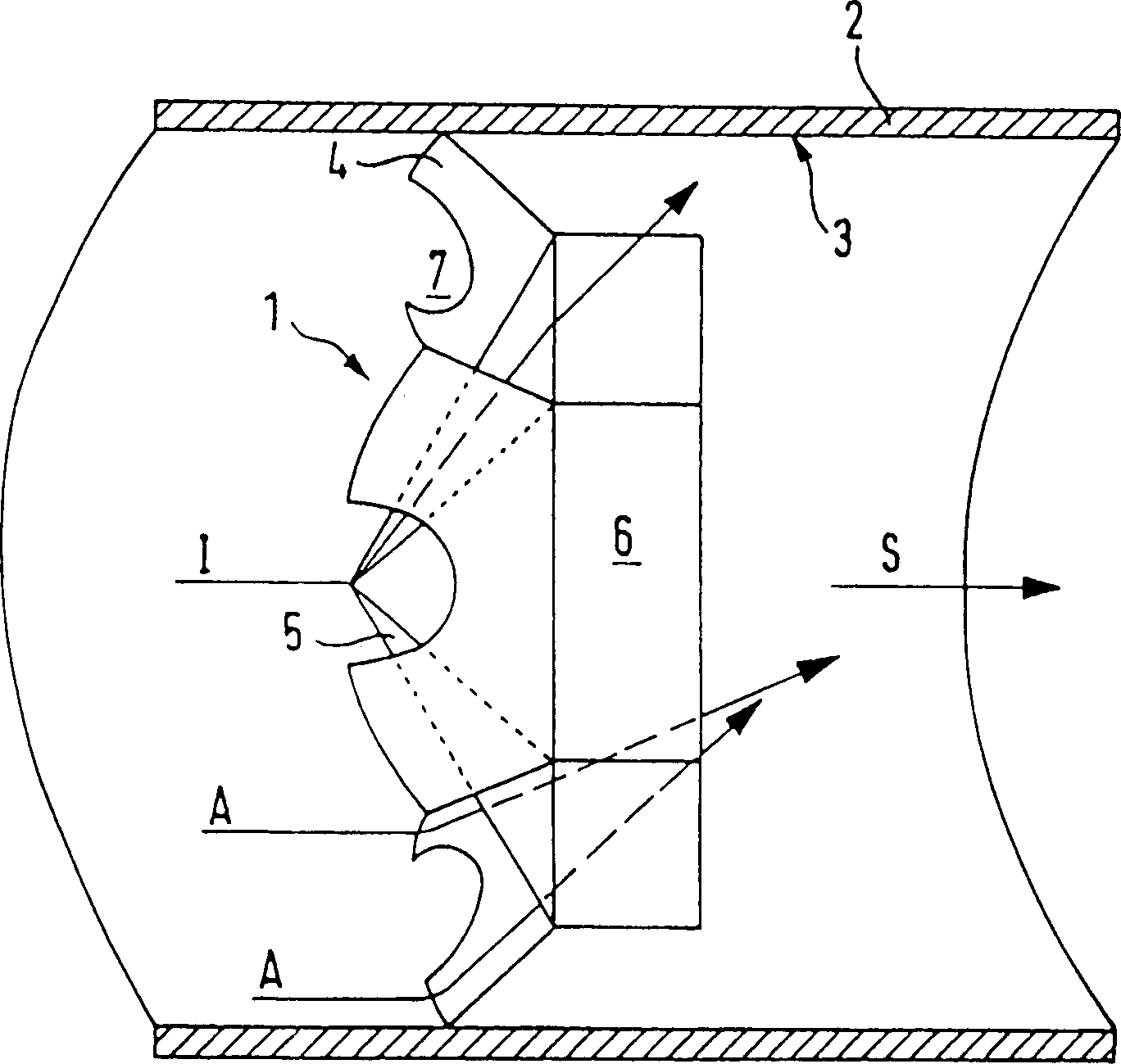
[0029] figure 1 A mixing element 1 according to the invention is shown schematically in side view, which is installed in a line 2, for example an exhaust pipe of an internal combustion engine (not shown). Exhaust gases from an internal combustion engine (not shown) are passed into an exhaust pipe 2 in which the mixing element 1 is arranged so as to lie approximately in one plane while deflecting part of the outer flow A adjacent the inner surface 3 of the duct 2 towards the inside , while part of the inner flow I is turned outward.

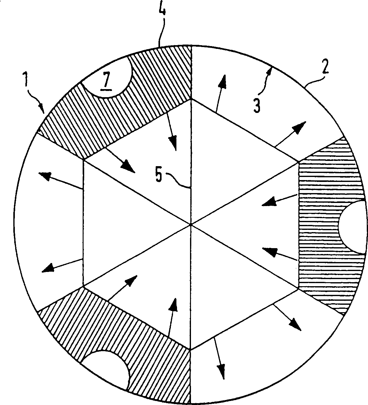
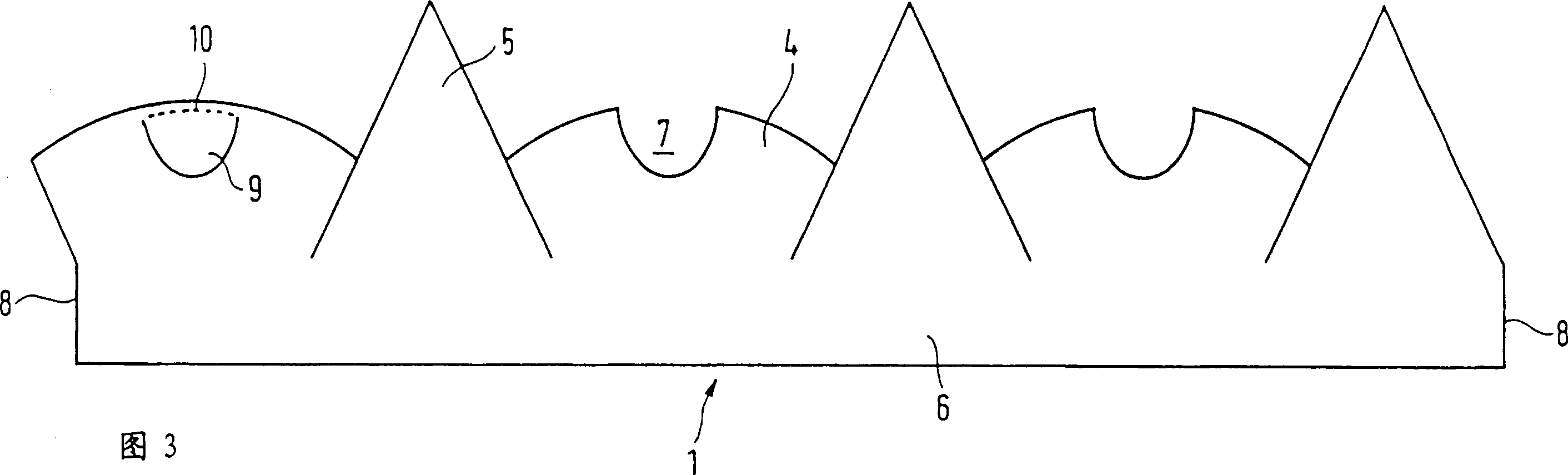
[0030] For this purpose, the mixing element 1 according to this exemplary embodiment has in each case 3 outer guide surfaces 4 and 3 inner guide surfaces 5, as from figure 2 and 3, the outer guide surface 4 resembles a trapezoid, while the inner guide surface 5 is triangular. The outer guide surface 4 serves to divert the outer flow A towards the inside; the inner guide surface 5 serves to divert the inner flow I towards the outside. In partic...


PUM


Abstract

The invention relates to a mixer element (1) for a fluid that is guided in a pipe (2), especially a mixer element that is used in the exhaust pipe of an internal combustion engine. Parts of the outer current A that is adjacent to the inner surface (3) of the pipe (2) are guided towards the interior by means of an outer guide section (4) and at the same time and in an approximately common plane parts of the inner current I are guided towards the exterior by means of an inner guide section (5). The use of the entire inner surface (3) of the pipe (2) for the purpose of cooling is preferably guaranteed by at least one opening (7) that is provided in the outer guide surface (4). The invention provides a simple means for obtaining a homogeneous temperature distribution and good cooling of a fluid that is guided in a pipe. The inventive mixer element (1) is especially distinguished from known mixer elements by its compact construction.

Description

technical field [0001] The invention relates to a mixing element for a fluid guided in a duct and to a duct, in particular an exhaust pipe of a motor vehicle, in which at least one such mixing element is arranged. Background technique [0002] Hot fluid introduced into the pipe, for example exhaust gas from an internal combustion engine, is supplied to a device, such as a three-way catalytic converter or NOx storage, this fluid has at least one outboard flow, which is cooled by the outer surface of the pipe, so There is a non-uniform temperature distribution across the entire section of the airflow. [0003] In order to make the uneven temperature distribution more even, it is known to place mixing elements in the pipe, which, viewed in cross-section of the pipe, either strip the cooler outside flow from the inner surface of the pipe and divert it to the inside The "peeling" element (hereinafter also referred to as the outer guiding surface) or the diverting element (herein...

Claims


Application Information

Patent Timeline
Patent Type & Authority Patents(China)
IPC IPC(8): F01N13/08B01D53/86B01F5/06F01N3/08F01N3/24F01N3/28F15D1/02F28F13/12
CPCF01N3/2892B01F5/061F01N3/0842B01F5/0616F01N2240/20B01F25/431B01F25/4315
Inventor 罗尔夫·布鲁克克特瑞恩·沙佩尔扬·霍德格逊
Owner EMITEC EMISSIONSTECHNIK
Why Eureka
Try Eureka