Drilling equipment for tunnel excavation
A drilling equipment and tunnel excavation technology, applied in tunnels, mining equipment, earthwork drilling, etc., can solve problems such as low efficiency and inability to accurately drill holes, increase drilling efficiency, avoid random flying, and reduce labor consumption Effect
- Summary
- Abstract
- Description
- Claims
- Application Information
AI Technical Summary
Problems solved by technology
Method used
Image
Examples
Embodiment 1
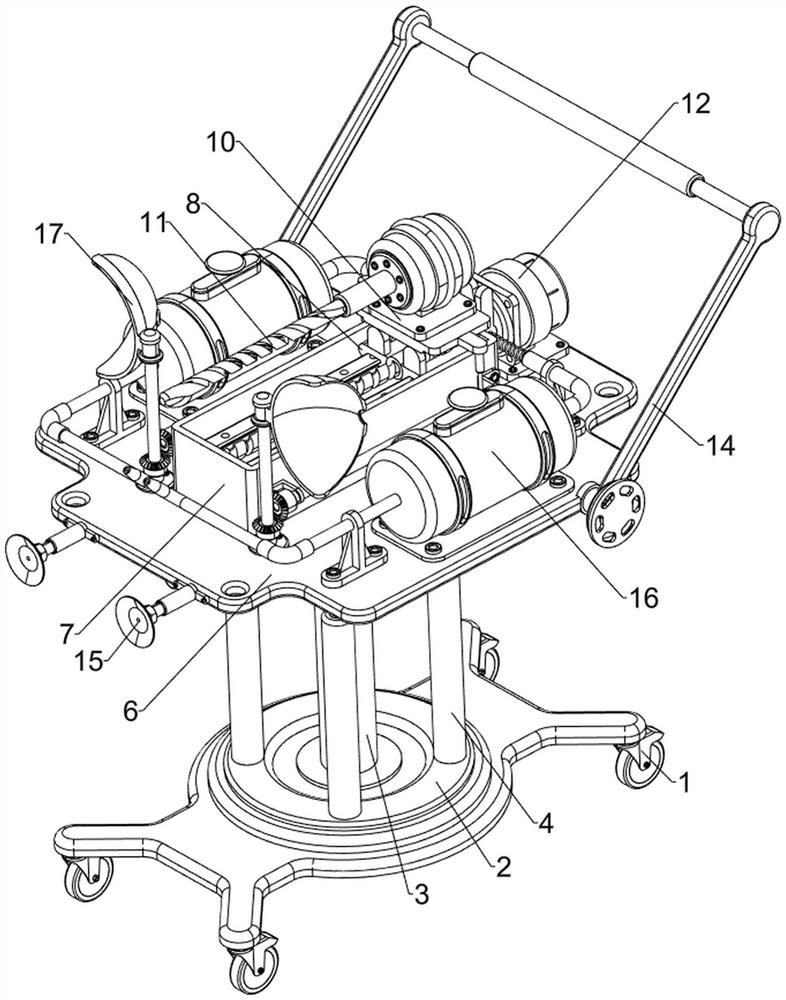
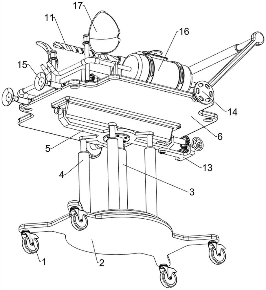
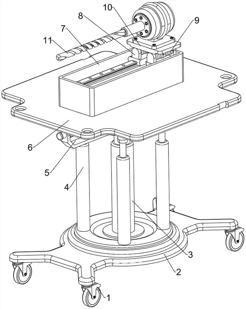
[0063] A kind of drilling equipment for tunnel excavation, such as Figure 1 to Figure 7 As shown, it includes a universal wheel 1, a base 2, a hydraulic cylinder 3, a first guide seat 4, a connecting frame 5, a mounting plate 6, a second guide seat 7, a slider 8, a buffer spring 9, a mounting table 10, an electric drill 11. The automatic drilling mechanism 12 and the angle adjustment mechanism 13, the left and right sides of the bottom of the base 2 are symmetrically provided with universal wheels 1 in front and rear, the top of the base 2 is provided with a hydraulic cylinder 3, and the top of the base 2 is provided with four first guide seats 4 , a connecting frame 5 is slidably connected between the top of the first guide seat 4, the top of the connecting frame 5 is hingedly provided with a mounting plate 6, the bottom of the connecting frame 5 is connected with the top end of the telescopic rod of the hydraulic cylinder 3, and the top of the mounting plate 6 is provided with...
Embodiment 2
[0068] On the basis of Example 1, as figure 1 , figure 2 , Figure 8 to Figure 12 As shown, it also includes a hand push mechanism 14. The hand push mechanism 14 includes a mounting plate 141, a spur gear 142, a mounting frame 143, a locking tooth 144, a first return spring 145 and a hand lever 146. The front and rear of the right part of the mounting plate 6 Both sides are connected with the mounting plate 141 through the receiving rod. The outer side of the inner wall of the mounting plate 141 is connected with the receiving rod. The receiving rod is rotatably provided with a spur gear 142, and the spur gear 142 will be located in the mounting disk 141. Between the spur gears 142 A handle rod 146 is connected, and mounting brackets 143 are symmetrically arranged on the inner side of the mounting plate 141. The mounting brackets 143 are slidably provided with clamping teeth 144, and a first return spring is connected between the clamping teeth 144 and the bottom of the moun...
Embodiment 3
[0072] On the basis of Example 2, as figure 1 , figure 2 , Figures 13 to 16 As shown, it also includes a dust removal mechanism 16. The dust removal mechanism 16 includes a support frame 161, a liquid storage tank 162, a support bracket 163, an ejection pipe 164, a cam 165, a contact plate 166, a third return spring 167 and a guide pipe 168, The top of the mounting plate 6 is provided with support frames 161 on both sides. The top of the support frame 161 is provided with a liquid storage tank 162. The top of the liquid storage tank 162 is provided with a rotary cover. The output shaft of the servo motor 122 is provided with a cam 165. The left and right sides of the top of the mounting plate 6 are symmetrically provided with support brackets 163 in the front and rear. The upper part of the left support bracket 163 is connected with an ejection pipeline 164, and the right side of the ejection pipeline 164 is connected with the liquid storage tank 162. The right support brac...
PUM
 Abstract
Description
Claims
Application Information
 - R&D
- Intellectual Property
- Life Sciences
- Materials
- Tech Scout
- Unparalleled Data Quality
- Higher Quality Content
- 60% Fewer Hallucinations
Browse by: Latest US Patents, China's latest patents, Technical Efficacy Thesaurus, Application Domain, Technology Topic, Popular Technical Reports.
© 2025 PatSnap. All rights reserved.Legal|Privacy policy|Modern Slavery Act Transparency Statement|Sitemap|About US| Contact US: help@patsnap.com


