
Magnetic drive pump with anti-falling structure

A magnetic pump and anti-shedding technology, which is applied to parts, pumps, and pump components of pumping devices used for elastic fluids, can solve problems such as loose screws or misalignment, overall vibration, and structural shedding, and achieve weight reduction. Improves stability and impact resistance and reduces production costs

Inactive Publication Date: 2022-08-05
陈汝
View PDF0 Cites 0 Cited by
  • Summary
  • Abstract
  • Description
  • Claims
  • Application Information

AI Technical Summary

Problems solved by technology

[0003] However, in the prior art, the existing magnetic pump is mainly connected to the base through the use of screws and nuts, so the tightness of the connection between the magnetic pump and the base is related to the structural strength of the screw used. Once the screw or If the nut is loose during use, it will directly lead to the loosening of the whole structure. At the same time, since the magnetic pump is equipped with a motor with a large power, and the motor will vibrate with a large amplitude and high frequency during operation, so In actual use, the vibration of the motor is transmitted to the pump head synchronously through the connecting frame, which causes the overall vibration. When the vibration of the entire pump body reaches a certain period of time, it may cause loosening or misalignment of the screws and screws, which in turn causes Misalignment and falling off of the overall structure, and the use of screws and screw rods requires manual fixing of the motor, connecting frame and pump head when assembling the magnetic pump, and then installation, which may also happen during the installation process The problem of part of the structure falling off

Method used


Image

  • Magnetic drive pump with anti-falling structure
  • Magnetic drive pump with anti-falling structure
  • Magnetic drive pump with anti-falling structure

Examples


Embodiment 1

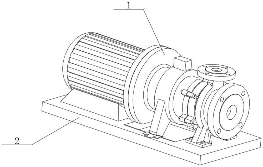
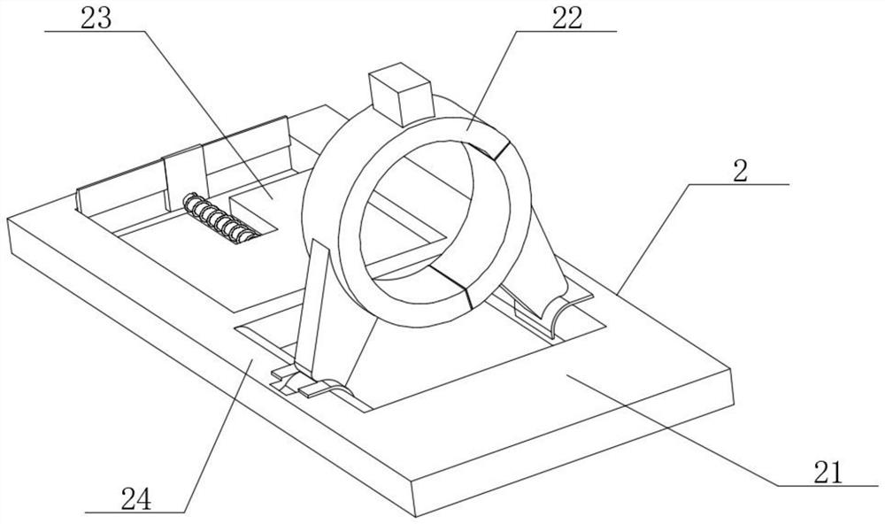
[0037] like figure 1 and figure 2 As shown, the present invention provides a technical solution: a magnetic pump with an anti-shedding structure, comprising a magnetic pump body 1, the bottom of the magnetic pump body 1 is provided with an anti-dropping structure 2, and the anti-dropping structure 2 includes a rectangular base 21 , the connecting frame support frame 22, the motor limiting frame 23 and the adjusting side post 24, the connecting frame supporting frame 22 is installed on the top of the rectangular base 21, the motor limiting frame 23 is installed inside the rectangular base 21, and the adjusting side post 24 is installed on the connecting frame At the junction of the support structure 22 and the rectangular base 21 , the connecting frame support structure 22 is located in the middle of the rectangular base 21 , and the motor limiting structure 23 is located at one end of the rectangular base 21 .

[0038] In this embodiment, the connecting frame supporting stru...

Embodiment 2

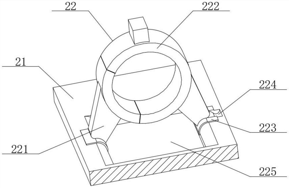
[0040] like Figure 1-4 As shown, the connecting frame support structure 22 includes a fixed bracket 221 and a movable bracket 222, the fixed bracket 221 is located on one side of the rectangular base 21, the movable bracket 222 is located on the other side of the rectangular base 21, and the top of the movable bracket 222 is connected to the fixed bracket 221. The top is connected, a limit card 223 is set at the intersection of the movable bracket 222 and the rectangular base 21 , and a limit recess 224 is set at the intersection of the limit card 223 and the rectangular base 21 , and the limit recess 224 is located on the upper surface of the rectangular base 21 One side of the limit card 223 is provided with a fixed plate 225, and a through hole 226 is opened at the intersection of the rectangular base 21, the fixed bracket 221 and the movable bracket 222, and the through hole 226 is located below the fixed bracket 221 and the movable bracket 222. The plate 225 is located o...

Embodiment 3

[0043] like figure 2 and Figure 5 As shown, the adjusting side post 24 includes a central rotating shaft 241, a rotating ring 242, a butting plate 243 and a buffer side plate 244. The rotating ring 242 is sleeved on the outer wall of the central rotating shaft 241, and one end of the butting plate 243 is connected to the outer wall of the rotating ring 242. , one end of the buffer side plate 244 is connected to the outer wall of the butt plate 243, the buffer side plate 244 is located on one side of the butt plate 243, the top of the butt plate 243 and the buffer side plate 244 are connected to the inside of the support rod 2221, and the central rotating shaft 241 is installed inside the rectangular base 21 .

[0044] In this embodiment, the central rotating shaft 241 serves as the circular shape of the entire adjusting side post 24, and the rotating ring 242 is connected to the supporting rod 2221 in the movable bracket 222 through the butting plate 243 and the buffer side...


PUM


Abstract

The invention provides a magnetic drive pump with an anti-falling structure, and relates to the technical field of magnetic drive pumps, the magnetic drive pump comprises a magnetic drive pump body, an anti-falling framework is arranged at the bottom of the magnetic drive pump body, and the anti-falling framework comprises a rectangular base, a connecting frame supporting framework, a motor limiting framework and an adjusting side column; the connecting frame supporting framework is installed on the top of the rectangular base. The connecting frame supporting framework and the motor limiting framework are connected through the rectangular base, so that impact force and vibration force borne by the two frameworks can be dispersed everywhere, and the stability and impact resistance of the whole anti-falling framework can be improved; meanwhile, the joints of the connecting frame supporting framework and the rectangular base and the joints of the motor limiting framework and the rectangular base are arranged to be in a semi-hollowed-out state, the whole rectangular base can be fixed conveniently, meanwhile, the weight of the whole anti-falling framework can be reduced, and the manufacturing cost of the anti-falling framework is reduced by reducing the using amount of materials.

Description

technical field [0001] The invention relates to the technical field of magnetic pumps, in particular to a magnetic pump with an anti-dropping structure. Background technique [0002] Magnetic pump (also known as magnetic drive pump) is mainly composed of pump head, magnetic drive (magnetic cylinder), motor, base and other parts. It is composed of an isolation sleeve. When the motor drives the outer magnetic rotor to rotate through the coupling, the magnetic field can penetrate the air gap and the non-magnetic material isolation sleeve to drive the inner magnetic rotor connected to the impeller to rotate synchronously, so as to realize the non-contact synchronous transmission of power. The dynamic sealing structure that is easy to leak is converted into a static sealing structure with zero leakage. Since the pump shaft and the inner magnetic rotor are completely closed by the pump body and the isolation sleeve, the problems of "running, running, dripping and leaking" are comp...

Claims


Application Information

Patent Timeline
Patent Type & Authority Applications(China)
IPC IPC(8): F04D13/06F04D29/62F04D29/66
CPCF04D13/06F04D29/62F04D29/66
Inventor 陈汝
Owner 陈汝
Learn More