Immersed tube joint floating condition calibration method

A calibration method and tube section technology, applied in complex mathematical operations, instruments, measuring devices, etc., can solve problems such as poor floating state calibration accuracy, reduce costs and difficulties, improve floating state calibration accuracy, and improve sinking installation accuracy. Effect

Pending Publication Date: 2022-08-05
CCCC FIRST HARBOR ENG +1
View PDF0 Cites 1 Cited by
  • Summary
  • Abstract
  • Description
  • Claims
  • Application Information

AI Technical Summary

Problems solved by technology

[0007] Aiming at the deficiencies in the related technologies, the present invention provides a method for calibrating the floating state of immersed tube joints, which aims to solve the problem that the existing calibra

Method used


Image

  • Immersed tube joint floating condition calibration method
  • Immersed tube joint floating condition calibration method
  • Immersed tube joint floating condition calibration method

Examples


Embodiment 1

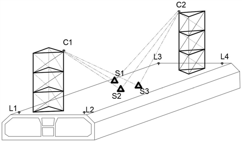
[0053] refer to figure 2 As shown, the present invention provides a method for calibrating a floating state of an immersed tube section, comprising the following steps:

[0054] 1) Prefabricate the pipe section in the dry dock area and establish the pipe joint coordinate system. At least three non-collinear characteristic points S1, S2 and S3 of the middle section of the pipe top are arranged in the middle section of the top surface of the pipe section, and the three pipe tops are calibrated respectively. The three-dimensional coordinates of the mid-section feature points S1, S2, and S3 in the pipe joint coordinate system; further, the three pipe top mid-section characteristic points S1, S2, and S3 can be dispersed to correspond to different positions in the pipe section width direction, and the distance from each other should be as large as possible Preferably, two feature points can be arranged at both ends of the pipe section in the width direction, three feature points in...

Embodiment 2

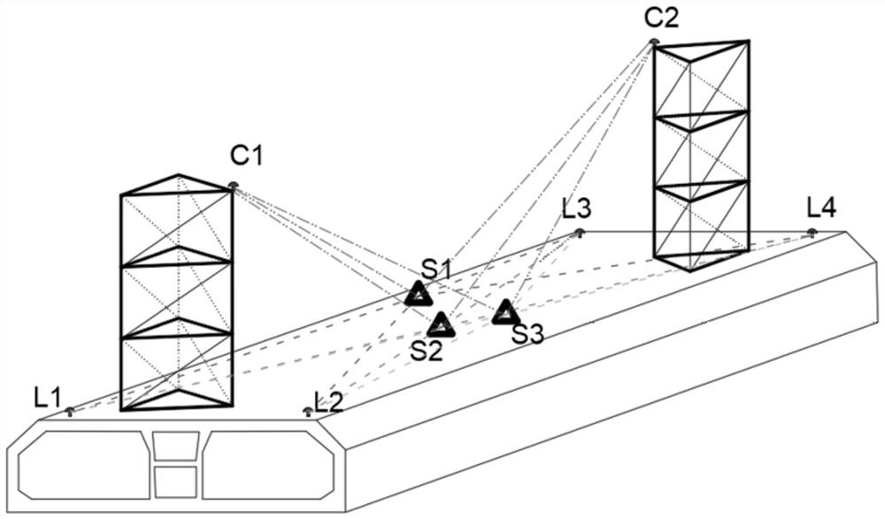
[0069] refer to image 3 As shown in the figure, the present invention also provides a method for calibrating the floating state of the immersed tube section. On the basis of the first embodiment, in order to ensure the robustness and reliability of the solution results, a spatial network is established to measure the characteristic points of the tower top. Calibration includes the following steps:

[0070] 1) Prefabricate the pipe section in the dry dock area and establish the pipe joint coordinate system, and arrange a pipe top feature point at each of the four corners of the top surface of the pipe section, denoted as L1, L2, L3, and L4, respectively. The three-dimensional coordinates of the feature points L1, L2, L3, and L4 at the top of each pipe in the pipe joint coordinate system; at least three non-collinear feature points S1, S2, S3 in the middle section of the pipe top are arranged in the middle section of the top surface of the pipe section. It should be noted that...


PUM


Abstract

The invention belongs to the technical field of engineering measurement, and relates to an immersed tube joint floating state calibration method. The floating state calibration method comprises the steps that a pipe joint coordinate system is established in a dry dock area, at least three non-collinear pipe top middle section feature points are arranged on the middle section of the top face of a pipe joint, and three-dimensional coordinates of the non-collinear pipe top middle section feature points in the pipe joint coordinate system are calibrated; the pipe joint is moved to an outfitting area, the head end and the tail end of the top face of the pipe joint are each provided with a measuring tower, tower top feature points are arranged, the spatial distances between the three pipe top middle section feature points and the two tower top feature points are measured, the three-dimensional coordinates of the three pipe top middle section feature points in a pipe joint coordinate system are combined, calculation is carried out through a spatial distance intersection method, and the three-dimensional coordinates of the three pipe top middle section feature points in the pipe joint coordinate system are calculated. And three-dimensional coordinates of the two tower top feature points in the pipe joint coordinate system are obtained. The method is easy to operate, calibration of the tower top feature points of the measuring tower can be completed only through distance measurement, the problem that the floating state calibration precision is poor due to the fact that an existing pipe joint calibration method is affected by posture changes when the pipe joint floats is solved, and the measurement calibration cost and difficulty are reduced.

Description

technical field [0001] The invention belongs to the technical field of engineering measurement, and in particular relates to a method for calibrating a floating state of a pipe section of an immersed tube. Background technique [0002] At present, most of the immersed pipe sections are installed by the measuring tower method, that is, a measuring tower is installed at the head and tail ends of the pipe top of the pipe section, the characteristic points of the tower top are arranged on the top of the measuring tower, and GNSS positioning equipment is installed; During the subsidence installation of the sections, all the pipe sections will be submerged below the water surface, and the immersed pipe sections can only be positioned by the GNSS positioning equipment on the characteristic point of the tower top at a certain height above the water surface, so as to guide the subsidence and installation of the immersed pipe sections. . Therefore, it is necessary to pre-calibrate th...

Claims


Application Information

Patent Timeline
IPC IPC(8): G01B21/00G01B21/02G06F17/12
CPCG01B21/00G01B21/02G06F17/12
Inventor 孙阳阳李进潘立文姚延焕孙竹徐良杜闯曹红涛
Owner CCCC FIRST HARBOR ENG
Why Eureka
Try Eureka