
Transformer winding state diagnosis method, device and system, equipment and medium

A state diagnosis and transformer technology, applied in the field of power system, can solve problems such as lack of transformer winding deformation fault, and achieve the effects of flexible and diverse signal modes, low voltage level, and convenient signal injection

Pending Publication Date: 2022-08-05
YUNNAN POWER GRID CO LTD ELECTRIC POWER RES INST
View PDF0 Cites 0 Cited by
  • Summary
  • Abstract
  • Description
  • Claims
  • Application Information

AI Technical Summary

Problems solved by technology

[0004] The main purpose of the present invention is to provide a transformer winding state diagnosis method, device and system, equipment and media, which can solve the lack of a reliable and effective online monitoring method for transformer winding deformation faults in the prior art, so as to realize the detection of transformer windings. The problem of real-time monitoring of winding state

Method used


Image

  • Transformer winding state diagnosis method, device and system, equipment and medium
  • Transformer winding state diagnosis method, device and system, equipment and medium
  • Transformer winding state diagnosis method, device and system, equipment and medium

Examples


Embodiment Construction

[0055] The technical solutions in the embodiments of the present invention will be clearly and completely described below with reference to the accompanying drawings in the embodiments of the present invention. Obviously, the described embodiments are only a part of the embodiments of the present invention, but not all of the embodiments. Based on the embodiments of the present invention, all other embodiments obtained by those of ordinary skill in the art without creative efforts shall fall within the protection scope of the present invention.

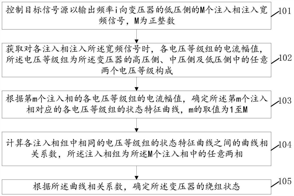
[0056] see figure 1 , figure 1 It is a flowchart of a method for diagnosing a winding state of a transformer in an embodiment of the present invention, such as figure 1 The shown method specifically includes the following steps:

[0057] 101. Control the target signal source to inject broadband signals into M injection phases on the low-voltage side of the transformer at the output frequency i, where M is a positive integer;

[005...


PUM


Abstract

The embodiment of the invention discloses a method, device and system for diagnosing the winding state of a transformer, equipment and a medium. The method comprises the steps that a target signal source is controlled to inject broadband signals to M injection phases on the low-voltage side of the transformer at the output frequency i; acquiring the current amplitude of each voltage level group when the broadband signal is injected into each injection phase; according to the current amplitude of each voltage grade group of the mth injection phase, determining a state characteristic curve of each voltage grade group corresponding to the mth injection phase, m being 1 to M; calculating a curve correlation coefficient between the state characteristic curves of the same voltage grade group in each injection phase group; and determining the winding state of the transformer according to the curve correlation coefficient. By means of the mode, signal injection is convenient, the voltage grade of the low-voltage side of the transformer is low, the system impedance of the low-voltage line side is large, broadband signals can be injected into the transformer conveniently, the amplitude of current flowing into and out of the transformer can be obtained online in real time, and the winding fault diagnosis accuracy is higher.

Description

technical field [0001] The present invention relates to the technical field of power systems, and in particular, to a method, device and system for diagnosing a winding state of a transformer, equipment and medium. Background technique [0002] Large-scale transformers are the key equipment in the power system. The sudden failure of the transformer during operation seriously affects the safety and stability of the power system, which can cause major asset losses and large-scale power outages. Transformer accidents show that winding deformation is one of the main causes of accidents. Traditionally, the winding deformation fault monitoring is carried out by injecting signals from the high-voltage side capacitor bushing and neutral line of the transformer. Due to the small capacitance of the bushing, it is not conducive to signal injection, and due to the large impedance of the transformer medium and low-voltage sides, the injected signal flows to the system. The high-voltage ...

Claims


Application Information

Patent Timeline
Patent Type & Authority Applications(China)
IPC IPC(8): G01R31/62
CPCG01R31/62
Inventor 刘红文钱国超赵现平聂鼎张春丽杨金东杨莉邓正东
Owner YUNNAN POWER GRID CO LTD ELECTRIC POWER RES INST
Learn More