Projection screen and projection system

A projection screen and a part of technology, applied in the field of projection screens and projection systems, can solve the problems of low brightness of projection screens

Pending Publication Date: 2022-08-05
QINGDAO HISENSE LASER DISPLAY CO LTD
View PDF0 Cites 0 Cited by
  • Summary
  • Abstract
  • Description
  • Claims
  • Application Information

AI Technical Summary

Problems solved by technology

[0006] The purpose of the present invention is to provide a projection screen, which is used to solve the problem of low brightness of the

Method used


Image

  • Projection screen and projection system
  • Projection screen and projection system
  • Projection screen and projection system

Examples


Example Embodiment

[0057] Embodiment 1 of the projection screen provided by the present invention:

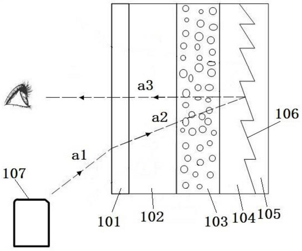
[0058] In the field of ultra-short-focus laser projection display, in order to achieve better brightness and display effect, a projection screen including a Fresnel lens layer is generally selected and used with a projector. This projection screen is characterized by high gain and small viewing angle. And has a certain anti-environmental light effect. The projection screen in the prior art generally includes a surface layer, a coloring layer, a diffusion layer, a Fresnel lens layer and a reflective layer that are arranged in sequence, and the light emitted by the projector passes through the projection screen twice during the incident and exit process. The coloring layer, the dark dye in the coloring layer will absorb a certain amount of light, thereby causing the loss of light energy, and finally making the brightness of the projection screen lower.

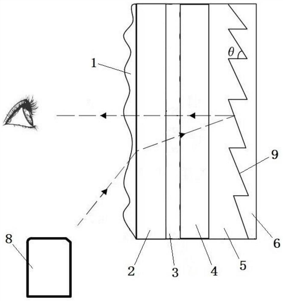
[0059] In view of the above reasons, the pr...

Example Embodiment

[0080] Embodiment 2 of the projection screen provided by the present invention:

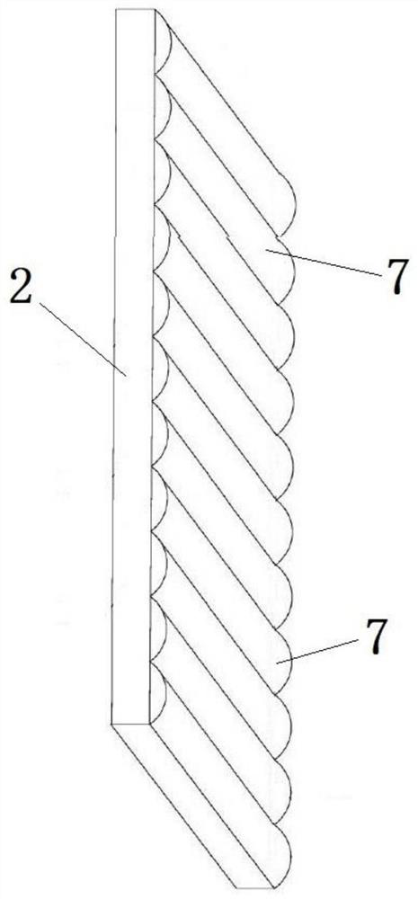
[0081] The difference from Example 1 is that: Figure 5 As shown, the light-scattering layer 3 is a base layer 12, and the base layer 12 is made of UV glue. Because the UV glue has elasticity, the base layer 12 can be curled, thereby making the light-scattering layer 3 curlable. The side of the base layer 12 away from the first support layer 2 is provided with a plurality of long grooves 13, the long grooves 13 are linear grooves, and the long grooves 13 are semicircular grooves, that is, the long grooves 13 are intercepted by a plane perpendicular to its extending direction. The shape of the simulated cross-section is a semicircle, and in the longitudinal extension direction of the long groove 13, the size of the simulated cross-section is the same everywhere, and the long groove 13 is cut by a plane perpendicular to its extension direction. Located on the side of the arc away from the first su...

Example Embodiment

[0087] Embodiment 3 of the projection screen provided by the present invention:

[0088] The difference from Example 1 is that: Image 6 and Figure 7 As shown, the diffusion layer is provided with two layers, namely a first diffusion layer and a second diffusion layer. The first diffusion layer includes a first support layer 2 and a layer of light scattering layer 3 arranged on the first support layer 2. The second diffusion layer The diffusion layer includes a second support layer 4 and a layer of light-scattering layer 3 arranged on the second support layer 4, the two light-scattering layers 3 are located between the first support layer 2 and the second support layer 4, and the two light-scattering layers 3 pass through OCA glue for fixing. After the two light-scattering layers 3 are bonded and fixed, a plurality of cavities for accommodating air are formed between the elongated protrusions of the two light-scattering layers 3 together.

[0089] It should be noted that t...


PUM

PropertyMeasurementUnit
Diameter rangeaaaaaaaaaa

Abstract

The invention discloses a projection screen and a projection system, relates to the technical field of projection screens, and is used for solving the problem of low brightness of a projection screen in the prior art. The projection system comprises a projector and a projection screen, the projection screen comprises a Fresnel lens layer, a reflecting layer and at least one diffusion layer, the Fresnel lens layer and the reflecting layer are arranged in a stacked mode, the diffusion layer is arranged on the side, away from the reflecting layer, of the Fresnel lens layer, and the projection screen further comprises a cavity used for containing gas; the diffusion layer comprises a first supporting layer and a plurality of astigmatism structures arranged on the first supporting layer, and the astigmatism surfaces, away from the first supporting layer, of the astigmatism structures serve as a part of the side wall of the cavity; dark dyes and reflecting materials are distributed in the reflecting layer.

Description

technical field [0001] The present invention relates to the technical field of projection screens, in particular to a projection screen and a projection system. Background technique [0002] In the field of projection display, especially in the field of ultra-short-focus laser projection display, in order to achieve better brightness and display effect, projectors are generally used with projection screens with Fresnel microstructures. [0003] like figure 1 As shown, the above-mentioned projection screen includes a surface layer 101, a coloring layer 102, a diffusing layer 103, a Fresnel lens layer 104 and a reflective layer 105 that are arranged in sequence. The surface layer 101 is used to protect the projection screen, and the coloring layer 102 is distributed in the There are dark dyes to improve the contrast of the projection screen, the diffusion layer 103 is used to diffuse the light entering the projection screen, the Fresnel lens layer 104 is provided with a refle...

Claims


Application Information

Patent Timeline
IPC IPC(8): G03B21/602G03B21/60G03B21/58
CPCG03B21/602G03B21/60G03B21/58G03B21/56
Inventor 冯宇侯蕊钟强王超
Owner QINGDAO HISENSE LASER DISPLAY CO LTD
Why Eureka
Try Eureka