Compression-resistant fireproof cable

A technology of fireproof cable and fireproof layer, applied in the direction of insulated cables, cables, circuits, etc., can solve the problems of not being able to dissipate heat from cables, not having the function of auxiliary cable heat dissipation, etc., so as to avoid the spread of open fire and avoid direct contact wear and tear. , to avoid the effect of mutual interference

Pending Publication Date: 2022-08-05
张莉
View PDF0 Cites 0 Cited by
  • Summary
  • Abstract
  • Description
  • Claims
  • Application Information

AI Technical Summary

Problems solved by technology

[0004] The purpose of the present invention is to provide a pressure-resistant and fire-resistant cable to solve the problem in the above-mentioned background technology that when the cable itself is provided with a fire-resistant material, a corresponding armor structure will be provided on the outer surface of the cable to avoid excessive deformation of the cable. , but the outer side of the armor layer should be covered with rubber again for protection. Even if there is no corresponding rubber to cover the armor, the armor structure still cannot dissipate the heat of the cable itself when it is used as a compression structure, so The existing protective structure does not have the function of assisting the heat dissipation of the cable itself

Method used


Image

  • Compression-resistant fireproof cable
  • Compression-resistant fireproof cable
  • Compression-resistant fireproof cable

Examples


Embodiment 1

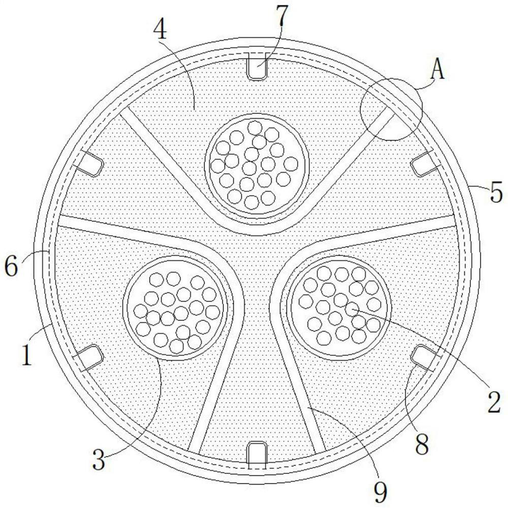
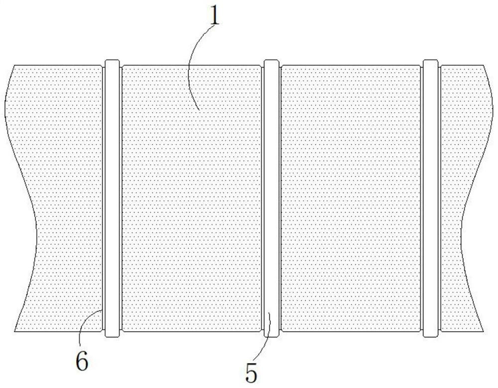
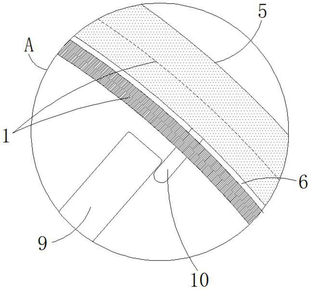
[0034] The fire cable includes a cable body 1 and a cable core 2 arranged inside the cable body 1. The outer wall of the cable core 2 is provided with a core protection layer 3, and the interior of the cable body 1 is filled with a flame retardant and fireproof layer 4. It also includes a protection sheet, the protection sheet fits into the outer wall of the cable body 1 through the positioning groove 6, and the outer surface of the protection sheet protrudes from the outer surface of the cable body 1, and the inner wall of the protection sheet is fixed with a splicing block 7, The splicing blocks 7 are equiangularly distributed with respect to the center of the cable body 1, and the splicing blocks 7 are matched with the splicing card slots 8. The splicing card slots 8 are opened in the cable body 1 and the flame retardant and fireproof layer 4, and the protective sheet is used for The cable body 1 is protected against compression. The anastomotic connection between the splici...

Embodiment 2

[0037] Different from the first embodiment, in order to avoid the phenomenon that the cable body 1 is twisted due to rolling during the placement process, in this embodiment, the protection sheet is the first protection patch 11, and the first protection patch is horizontally distributed. The axes of the sheet 11 and the cable body 1 are distributed parallel to each other, and the first protection patch 11 is distributed at an equal angle with respect to the center of the cable body 1, such as Figure 5-6 As shown, the first protection patch 11 is also a thermally conductive material, and on the basis of the protection and heat conduction effect of the protection ring 5 in the embodiment, the first protection patch 11 is also used to prevent the cable Body 1 rolls.

[0038] In this embodiment, the difference from Embodiment 1 is as follows. The heat dissipation device is a second metal strip 12 disposed inside the cable body 1. The end of the second metal strip 12 is also conn...

Embodiment 3

[0040] In the prior art, although there are some technologies in which a corresponding metal wire is arranged in the cable as the reinforcing structure of the cable, due to the aging of the cable and the deformation and damage of the cable caused by the external impact force, the cable core 2 runs under high load. The phenomenon of burning to produce open fire will occur, and at this time, these reinforcing structures not only cannot play a role in fire prevention, but also quickly conduct heat to other areas due to their thermal conductivity, resulting in faster burning of cables. Therefore, in this In the technical solution, in order to solve the above problem, the following solution is also provided. The protection sheet is the second protection patch 13. The second protection patch 13 is also equiangularly distributed with respect to the center of the cable body 1, and the second protection patch 13 is equiangularly distributed. The inner wall is fixed with a heat-conductin...


PUM


Abstract

A pressure-resistant fireproof cable disclosed by the present invention comprises a cable body and a cable core arranged in the cable body, the outer wall of the cable core is provided with a cable core protection layer, and a protection sheet is used for performing pressure-resistant protection on the cable body. The matching connection between the splicing clamping block and the splicing clamping groove is used for reinforcing the connection between the protection sheet and the cable body. According to the compression-resistant fireproof cable, firstly, anti-impact protection can be carried out on the exterior of the cable body by using the protection sheet, and anti-impact protection can be carried out on the interior of the cable by using the characteristic of elastic metal of the internal heat dissipation metal strips, and secondly, the metal strips and the protection sheet are connected through the heat conduction vertical strips, so that the heat dissipation performance of the cable is improved. Heat can be rapidly dissipated in a heat conduction mode, meanwhile, the characteristic that the memory alloy of the metal strip can recover to the original shape at high temperature can be utilized, when open fire occurs in the cable, the high temperature of the open fire is utilized to promote the metal strip to rapidly recover to the original shape and wrap an ignition point, and spread of the open fire is effectively avoided.

Description

technical field [0001] The invention relates to the technical field of cables, in particular to a compression-resistant fireproof cable. Background technique [0002] In the prior art, the large-scale combustion of cables is avoided as much as possible by adding flame-retardant materials to the cables. Although the cable material itself does not have good flammability, it is impacted and deformed by external pressure during aging of the line. And in the case of internal damage, the high heat collection of the cable core in the cable is still easy to cause high temperature fire inside the cable and the melting and spreading of the fireproof material itself. It is necessary to set up a corresponding compression structure for protection, but the existing similar structures still have the following problems in actual use: [0003] When the cable itself is provided with fireproof materials, a corresponding armoring structure will be installed on the outer surface of the cable to...

Claims


Application Information

Patent Timeline
IPC IPC(8): H01B7/42H01B7/17H01B7/295H01B7/18
CPCH01B7/428H01B7/421H01B7/17H01B7/295H01B7/18Y02A30/14
Inventor 张莉
Owner 张莉
Why Eureka
Try Eureka