A vibration damping device for a diaphragm coupling and a vibration damping method thereof

A diaphragm coupling and vibration damping device technology, which is applied in the direction of couplings, elastic couplings, non-rotational vibration suppression, etc., can solve the problem of no significant improvement in vibration reduction, increased diaphragm wear fatigue, and failure to achieve vibration reduction Effect and other issues, to achieve good vibration damping effect, avoid direct contact wear, and compact structure

Active Publication Date: 2022-03-11
JIANGSU UNIV OF SCI & TECH
View PDF13 Cites 0 Cited by
  • Summary
  • Abstract
  • Description
  • Claims
  • Application Information

AI Technical Summary

Problems solved by technology

[0004] The patent with the application number 201910519755.5 discloses a diaphragm coupling of triple diaphragm group, which connects the middle diaphragm group and the self-aligning bearing together, and utilizes the self-aligning performance of the self-aligning ball bearing to reduce the loss due to additional displacement. The additional load acting on the diaphragm can compensate for large angular displacement, axial displacement, and radial displacement, but the direct contact between the diaphragms in the diaphragm group of the diaphragm coupling will inevitably increase the diaphragm The wear and fatigue of the diaphragm, and the three sets of diaphragms only limit the random vibration in any direction and ease the impact vibration, but they cannot achieve a good vibration damping effect, and the vibration isolation characteristics of the diaphragm coupling are also used to evaluate the coupling An important parameter of performance, this type of diaphragm coupling has no significant improvement in vibration reduction and still needs continuous improvement

Method used


Image

  • A vibration damping device for a diaphragm coupling and a vibration damping method thereof
  • A vibration damping device for a diaphragm coupling and a vibration damping method thereof
  • A vibration damping device for a diaphragm coupling and a vibration damping method thereof

Examples


Embodiment Construction

[0038] The present invention is described in more detail below in conjunction with accompanying drawing example, further clarifies the present invention, should be understood that these embodiments are only for illustrating the present invention and are not intended to limit the scope of the present invention, after having read the present invention, those skilled in the art will understand the present invention Modifications of various equivalent forms of the invention all fall within the scope defined by the appended claims of the present application.

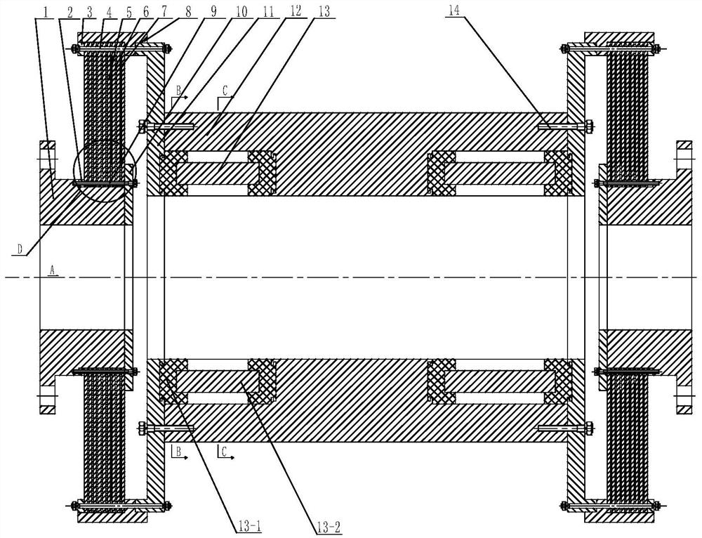
[0039] Such as Figure 1 to Figure 7 As shown, it is a vibration damping device for a diaphragm coupling of the present invention, including an intermediate shaft 12, which is a sleeve-shaped structure with a large diameter at both ends and a small diameter in the middle, and the two ends of the intermediate shaft 12 The intermediate flange 11 and the outer flange 8 are respectively successively connected, and the intermediat...


PUM


Abstract

A vibration damping device for a diaphragm coupling, comprising an intermediate shaft, the intermediate shaft is a sleeve-shaped structure with a large diameter at both ends and a small diameter in the middle, and the two ends are respectively connected with an intermediate flange and an outer flange, The intermediate flange and the intermediate shaft are connected by a plurality of bolts III, and a plurality of dynamic vibration absorbing members are evenly distributed along the circumferential direction in the large diameter hole of the intermediate shaft. A plurality of groups of diaphragms are arranged in the outer flange, and the diaphragm groups are connected with the intermediate flange and the outer flange through several bolts I. The diaphragm group consists of a plurality of diaphragms and a plurality of damping elements arranged in parallel and installed. The inner hole of the diaphragm group is sleeved with a flange I, the flange I is stepped, and a stopper is installed on the inner side of the diaphragm group. The blue I, the diaphragm group and the block are connected by several bolts II. The placement of the diaphragm group effectively increases the resonance bandwidth. The dynamic vibration absorption device coexists with axial vibration absorption and radial vibration absorption. Power transmission and structural strength.

Description

technical field [0001] The invention relates to a vibration damping device for a diaphragm coupling, in particular to a vibration damping structure and a vibration damping method for a diaphragm coupling, belonging to the field of vibration reduction and noise reduction for shaft couplings. Background technique [0002] With the rapid development of vibration reduction technology, higher requirements are put forward for the damping structure. How to reduce the vibration of mechanical equipment and systems, improve the life of the system and eliminate noise pollution has received more attention. Highly elastic couplings for ships have high-efficiency response characteristics while transmitting torque, and have a good vibration isolation effect on the power transmission system. Diaphragm flexible coupling is mainly composed of diaphragm, driving shaft and driven shaft shaft end, intermediate shaft with flange and connecting bolts, mainly plays the role of torque transmission, ...

Claims


Application Information

Patent Timeline
Patent Type & Authority Patents(China)
IPC IPC(8): F16D3/56F16F15/08
CPCF16D3/56F16F15/08
Inventor 温华兵钱徐芹渠浩袁桐桐
Owner JIANGSU UNIV OF SCI & TECH
Why Eureka
Try Eureka