Multi-stable velocity amplifying and frequency-increasing composite vibration energy harvester and its collection method

A vibration energy harvesting and speed amplification technology, which is applied to generators/motors, piezoelectric effect/electrostrictive or magnetostrictive motors, electrical components, etc., can solve the problem of low utilization rate, complicated magnetic field setting, and inability to miniaturize and other issues to achieve the effect of improving efficiency, increasing low-frequency work efficiency, and improving work efficiency

Active Publication Date: 2022-05-24
YANSHAN UNIV
View PDF11 Cites 0 Cited by
  • Summary
  • Abstract
  • Description
  • Claims
  • Application Information

AI Technical Summary

Problems solved by technology

[0003] In order to solve the deficiencies mentioned in the above-mentioned prior art, further increase the output power of the broadband multi-stable up-frequency compound vibration energy harvester, and improve the defects of complicated magnetic field setting, low utilization rate and inability to further miniaturize, the present invention provides a A multi-stable speed amplification and frequency-up compound vibration energy harvester, the collector can increase the relative speed of the transducer unit in the electromagnetic induction and friction nanogenerator through the motion amplification and direction change of the mechanical transmission, and increase the frequency of each cycle. The frequency of energy transfer between the inner low-frequency vibrator and the high-frequency piezoelectric transducer

Method used


Image

  • Multi-stable velocity amplifying and frequency-increasing composite vibration energy harvester and its collection method
  • Multi-stable velocity amplifying and frequency-increasing composite vibration energy harvester and its collection method
  • Multi-stable velocity amplifying and frequency-increasing composite vibration energy harvester and its collection method

Examples


specific Embodiment

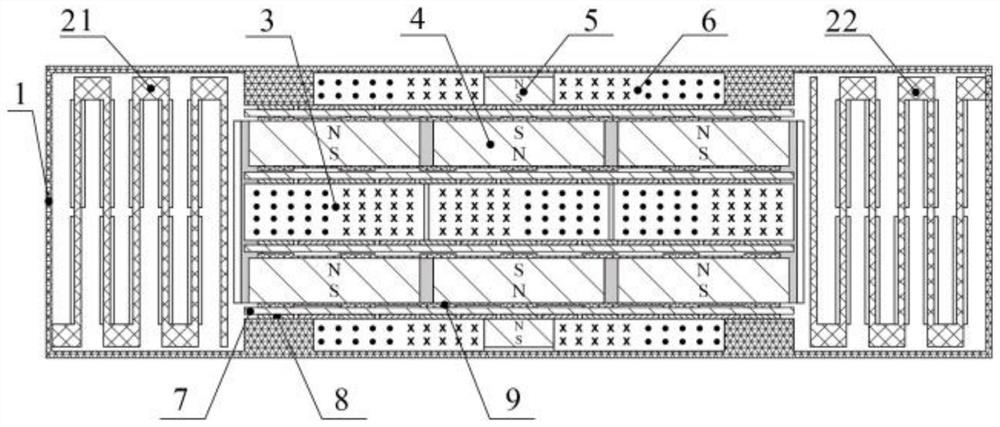
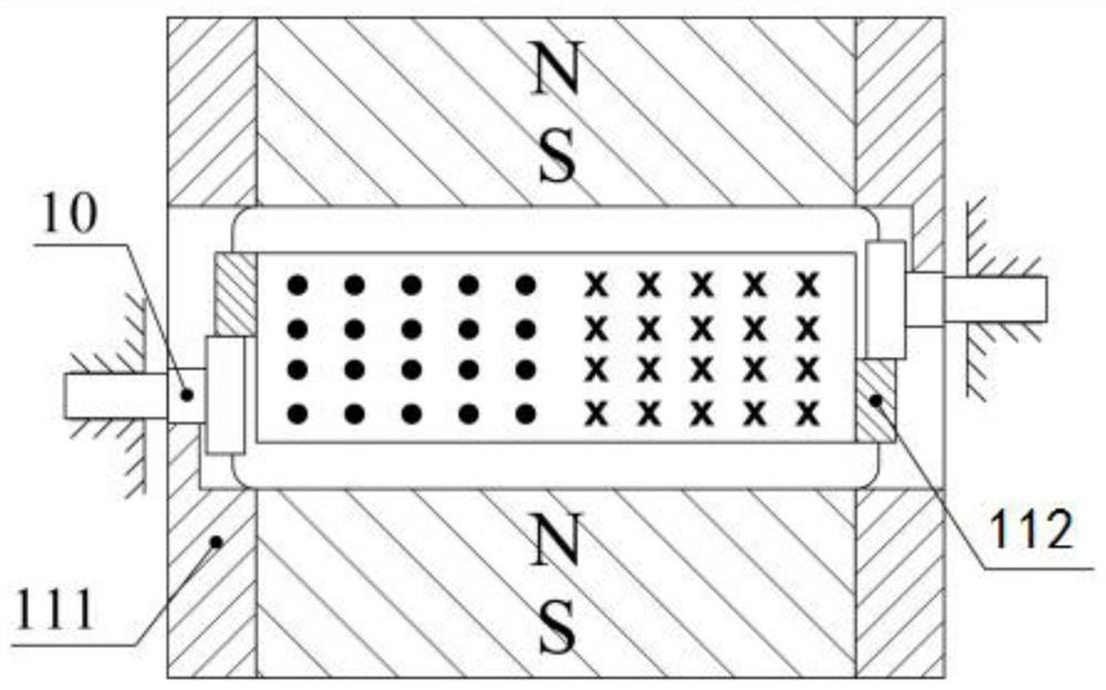
[0037] Referring to the drawings, the multi-stable motion amplifying and up-converting composite vibration energy harvester in the present invention includes a housing 1, a first high-frequency piezoelectric cantilever beam 21, a second high-frequency piezoelectric cantilever beam 22, and a movable induction coil Group 3, movable permanent magnet array 4, fixed permanent magnet array 5, fixed induction coil group 6, tetrafluoroethylene film 7, plane tooth comb electrode 8, nylon electrode 9, coaxial transmission gear 10, rack and permanent magnet array fixed Rack 111 and rack 112 .

[0038] The movable permanent magnet array 4 is formed by six rubidium iron boron permanent magnets divided into upper and lower rows and arranged according to the polarity shown in the drawings. The upper and lower rows of magnets are attached to the outer metal frame to prevent mutual attraction. The movable induction coil group 3 is located in the middle cavity of the movable permanent magnet a...


PUM


Abstract

The invention provides a multi-stable speed amplification frequency-up compound vibration energy collector and its collection method, which includes a casing, a movable induction coil group, a fixed induction coil group, a movable permanent magnet array, a fixed permanent magnet array, a second A high-frequency piezoelectric cantilever beam, a second high-frequency piezoelectric cantilever beam, a dielectric film, a planar comb electrode and a transmission mechanism; the first high-frequency piezoelectric cantilever beam and the second high-frequency piezoelectric cantilever beam are respectively arranged inner two ends. Through the motion amplification and direction change of the mechanical transmission, the collector can increase the relative speed of the transducer unit in the electromagnetic induction and friction nanogenerator and increase the frequency of energy transfer between the low-frequency vibrator and the high-frequency piezoelectric transducer in each cycle. . At the same time, the design of the magnetic field of the collector reduces the number of linear spring structures required to generate the seven-stable characteristic and improves the utilization rate of the magnetic field, thereby reducing the difficulty of production and assembly, and making the collector further miniaturized and integrated.

Description

technical field [0001] The invention belongs to the technical field of vibration energy collection, and in particular relates to a multi-stable speed amplification and up-frequency composite vibration energy collector and a collection method thereof. Background technique [0002] At present, the known broadband multi-stable up-frequency composite vibration energy harvesters mostly use a low-frequency oscillator to couple the vibration in the environment, and then transfer the kinetic energy of the low-frequency oscillator to the transducer with high natural frequency through collision or magnetic force. device structure, and then generate electrical energy through electromechanical coupling. In a single cycle, the energy transfer between the low frequency oscillator and the high frequency transducer is only one or two times, and the energy transfer efficiency is low. The multi-stable characteristic of the collector mainly depends on the action of the external magnetic field...

Claims


Application Information

Patent Timeline
Patent Type & Authority Patents(China)
IPC IPC(8): H02N2/18H02N1/04
CPCH02N2/188H02N1/04
Inventor 王辰王晨曦郝颖李哲李文强文桂林
Owner YANSHAN UNIV
Why Eureka
Try Eureka