Printed Broadband Terminal Antenna

A terminal antenna and broadband technology, which is applied in antennas, resonant antennas, antenna grounding devices, etc., can solve the problems that antennas cannot meet the requirements of broadband, miniaturization, and small space at the same time, and achieve easy processing and realization, simple structure, and increased Effect of Resonance Bandwidth

Inactive Publication Date: 2015-09-09
UNIV OF ELECTRONICS SCI & TECH OF CHINA
View PDF5 Cites 0 Cited by
  • Summary
  • Abstract
  • Description
  • Claims
  • Application Information

AI Technical Summary

Problems solved by technology

[0004] The purpose of the present invention is to provide a printed broadband terminal antenna that takes up less space, mainly to solve the problem that the antennas in the prior art cannot meet people's requirements for broadband and miniaturization at the same time

Method used


Image

  • Printed Broadband Terminal Antenna

Examples


Embodiment

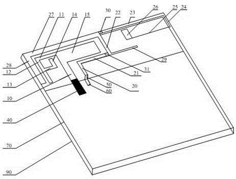
[0025] Such as figure 1 As shown, the printed broadband terminal antenna, including the printed circuit board 70, is arranged on the first bent metal strip group on one surface of the printed circuit board 70, forming an unclosed ring structure and surrounding the first bent metal strip group. Two bent metal strip groups, the microstrip feeder 40 connected to the first bent metal strip group, the grounding device connected to the second bent metal strip group; the printed board metal ground arranged on the other surface of the printed circuit board 70 90. There is also a metal-free area on the surface where the printed board metal ground 90 is located. This metal-free area is set in the printed board metal ground 90 and forms a metal-free area that is not closed by the printed board metal ground 90 at least on one side. , the metal-free area includes the corresponding area where the antenna line is orthographically projected onto the surface where the metal ground 90 of the pr...


PUM


Abstract

The invention discloses a printed broadband terminal antenna, and mainly solves a problem that an antenna in the prior art cannot satisfy people's requirements of broadband and miniaturization of the antenna at the same time. The printed broadband terminal antenna comprises a printed circuit board, a printed board metal platform disposed on a surface of the printed circuit board, and also comprises a first bending metal strips group and a second bending metal strips group disposed on the other surface of the printed circuit board, a microstrip feeder connected with an end of the first bending metal strips group, and an earthing device connected with the second bending metal strips group. The second bending metal strips group has a semi-enclosed cyclic structure and surrounds the first bending metal strips group. With the above scheme, the printed broadband terminal antenna achieves an objective of realizing antenna miniaturization while the bandwidth is guaranteed, and has very high utility value popularization value.

Description

technical field [0001] The invention relates to a terminal antenna, in particular to a printed broadband terminal antenna. Background technique [0002] The rapid popularization of mobile communication technology makes the communication between people overcome the barriers of time and space and becomes ubiquitous. The constantly updated electronic products make real-time information acquisition and exchange possible, providing people with portable and efficient Wireless communication services, and antennas are essential in these wireless communication services. At the same time, with the rapid development of personal communication services, people put forward more stringent requirements on the design of wireless products. These requirements are mainly reflected in two aspects: broadband and miniaturization. At present, the commonly used 3G civil communication system and the evolving 4G wireless communication system need antennas with wider bandwidths to obtain greater trans...

Claims


Application Information

Patent Timeline
Patent Type & Authority Patents(China)
IPC IPC(8): H01Q1/38H01Q1/48H01Q9/04H01Q13/08
Inventor 杨顺刘佳奇李乐伟王朗
Owner UNIV OF ELECTRONICS SCI & TECH OF CHINA
Why Eureka
Try Eureka